Glossary
J |
K |
Q |
Y |
Z |
|
Term |
Definition |
||||||||||||||||||||||||||
|
Sometimes called beam width, and in early versions of Echoview nominal angle. For a single acoustic beam, the angle between the half power points of the main lobe of the transducer beam pattern measured in degrees. If the beam is elliptical the 3dB beam angle is measured separately along the major and minor axes. Multibeam echosounders produce many individual acoustic beams each with a 3dB beam angle or two (minor and major axis). In Echoview, the 3 dB beam angle is defined independently for the minor axis and major axis on the Calibration page of the Variable Properties dialog box. For circular transducers the major and minor axis 3dB beam angles are equal. See: About calibration settings for more information. |
|||||||||||||||||||||||||||
|
The 3dB beam angle along the minor-axis. |
|||||||||||||||||||||||||||
|
The 3dB beam angle along the major-axis. |
|||||||||||||||||||||||||||
|
A group of 3D regions intended to show a pattern of systematic movement for detected schools. A 3D region track is a specific variant of the 3D polyline. See: About 3D region tracks for more information. |
|||||||||||||||||||||||||||
|
A group of 3D region tracks intended to capture the results of a single region track detection. |
|||||||||||||||||||||||||||
|
A point in three dimensional space, having latitude, longitude and depth. A 3D point will generally also have a valid time and sometimes an intensity. This is not a 3D object in Echoview but a part of other 3D objects. Viewed on a scene, 3D points can be seen as spheres in a 3D region track, 3D polyline, 3D single targets object or 3D fish tracks object and as vertices in any other type 3D object for example. |
|||||||||||||||||||||||||||
|
A group of 3D polylines resulting from a single import of 3D polylines. |
|||||||||||||||||||||||||||
|
Area backscattering coefficient sa (m2m-2)*. See also Nautical area scattering coefficient (NASC).
where:
See: ABC and NASC for more information. *MacLennan et al 2002 Table 1. |
|||||||||||||||||||||||||||
|
Absorption coefficient of sound in water in dB per unit distance (dB/m). See: About calibration settings and About Sonar calculator for more information. |
|||||||||||||||||||||||||||
|
Acoustic variable |
Variables that contain a time-series of measurements associated with the transmitted and received properties of pings. See: About variables for more information. |
||||||||||||||||||||||||||
|
The finish of the acquired time range for a 3D object. |
|||||||||||||||||||||||||||
|
The start of the acquired time range for a 3D object. |
|||||||||||||||||||||||||||
|
A property of 3D objects which defines the time over which the data for this object was acquired. An object may have a single acquired time (for a multibeam ping curtain for example. The acquired time for a group would be the time period covering all of its component objects. The acquired time is seen on the Time page of the (3D Object) Properties dialog box. |
|||||||||||||||||||||||||||
|
Active window |
The active window will have its title bar highlighted and will receive keyboard commands. |
||||||||||||||||||||||||||
|
An equirectangular projection in which the standard parallel is chosen individually for each object that is mapped, at the centroid of that object. As a result each object mapped experiences minimal distortion but when multiple objects are mapped they do not experience the same distortion. This is especially pertinent when multiple objects are added to scenes in Echoview. |
|||||||||||||||||||||||||||
|
Acoustic Doppler Current Profiler - a device using sonar data (in particular the frequency shift caused by the Doppler effect due to relative motion between transmitter and receiver) to measure water current velocities. |
|||||||||||||||||||||||||||
|
A calibration setting used on HTI echosounders. It is typically stored in HTI data files, but for some early versions of HTI data files it is not present. This occurred for 0.0 .INT files. Versions prior to Echoview 5.4 required the user to calculate and apply Aequip. Echoview now reads or automatically calculates this constant for other HTI file types. |
|||||||||||||||||||||||||||
|
The direction on ship which runs from bow to stern. Typically Simrad transducers have an alongship axis which is the equivalent of Echoview's minor-axis. Simrad may also refer to this axis as the 'longitudinal' axis. |
|||||||||||||||||||||||||||
|
Synonym for absorption coefficient. |
|||||||||||||||||||||||||||
|
The colored fill pattern that is displayed in an analysis domain when you complete an on-screen integration or an on-screen analysis of the analysis domain on an echogram. Hint: You can choose the analysis-hatching color for custom color schemes. To set the analysis-hatching color for a custom color scheme: open the color scheme in Echocolor; display the Miscellaneous page of the Palette Properties dialog box; and select the required color in the Analysis-hatching color box. |
|||||||||||||||||||||||||||
|
Data logged by an echosounder which attempts to predict the angular position of targets within the beam. Only returned by split-beam echosounders, these data are based upon differences in signal phase measured at different points on the transducer phase - from which the direction of an arriving wavefront is estimated. Very useful when working with single targets, angle data are all the same, generally less reliable than range measurements for the purposes of spatial measurements. |
|||||||||||||||||||||||||||
|
ANSI character encoding, typically for English characters. |
|||||||||||||||||||||||||||
Artificial intelligence is the theory and development of computer systems that are able to perform tasks or exhibit behavior requiring human intelligence such as visual perception and decision-making. (See also deep learning, machine learning and supervised learning.) |
|||||||||||||||||||||||||||
|
The direction on ship which runs from port to starboard. Typically Simrad transducers have an athwartship axis which is the equivalent of Echoview's major-axis. Simrad may also refer to this axis as the 'Transversal' axis. |
|||||||||||||||||||||||||||
|
Variables that contain a time series of measurements associated with the heading, roll, pitch, yaw and heave of a platform. Note: Only heading and roll variables are currently supported. See: About variables for more information. |
|||||||||||||||||||||||||||
|
A feature that is available to automatically maintain the display of the same, or nearest, time on echogram windows. See: Auto-synchronization of echograms for further information. |
|||||||||||||||||||||||||||
|
Azimuth is the angle between the beam axis and the stern-bow (or south-north) axis. See: About beam geometry and About transducer geometry for further information. |
|||||||||||||||||||||||||||
|
Scattered by a target back in the direction of the acoustic source. |
|||||||||||||||||||||||||||
|
A measure of the backscatter strength from the target, denoted by σbs (m2) Backscattering cross-section in m2 is defined* by:
A useful relationship is that of:
*MacLennan et al 2002 Table 1. |
|||||||||||||||||||||||||||
|
Background noise is the signal present at the output of the echosounder receiver when the transmitter is turned off. Background noise is also present when the echosounder is transmitting. Correction of the echo integral for background noise may be necessary where the signal to noise ratio is low. See: Use of background noise in Echoview for more information. |
|||||||||||||||||||||||||||
|
Sv_noise, NASC_noise, ABC_noise. |
|||||||||||||||||||||||||||
|
Data that falls within a bad data region. |
|||||||||||||||||||||||||||
|
A region containing data points that are affected by Analysis settings during analyses. See Region type and About analysis domains for further information. |
|||||||||||||||||||||||||||
A signal-processing mathematical method that allows data between two specific frequencies (f1 and f2) to pass (unaffected) and rejects (attenuates) data at other frequencies. |
|||||||||||||||||||||||||||
|
Chirp bandwidth The range of frequencies in a transmitted chirp. The bandwidth is often cited as Start frequency to Stop frequency e.g. 90-170 kHz. Transducer setting On Simrad Ex500 series echosounders a setting of this name can take the value of Narrow, Wide, or Auto which must be specified on the Calibration page of Variable properties dialog box for the Power to Sv or TS calculation. Note: This setting is not required for data from a Simrad Ex60 series echosounder. See also Pulse length. |
|||||||||||||||||||||||||||
|
A file that contains a sequence, or batch, of commands. Batch files are useful for storing sets of commands that are always executed together because you can simply enter the name of the batch file instead of entering each command individually. See your Windows help for information on creating batch files. |
|||||||||||||||||||||||||||
|
Bathymetric data extraction |
The process of obtaining bathymetric data (bottom picks) from echogram data in Echoview. See: Export file formats for more information. |
||||||||||||||||||||||||||
|
A constituent part of a multibeam ping. See: About sector plots and beams and About pings |
|||||||||||||||||||||||||||
|
The axis at the center of the acoustic beam. For single beam echosounders this is the same as the transducer axis. For multibeam echosounders each beam has its own axis. See: About beam geometry and About sector plots and beams for more details. |
|||||||||||||||||||||||||||
|
Position measured along the beam-axis. This is identical to range for targets on the beam-axis, but for targets not on the beam-axis it will typically be shorter than the range. See: About single target ranges for more information. |
|||||||||||||||||||||||||||
|
The compensation applied to a measured TS value correcting it for transducer directivity, that is for the location of the target within the transducer beam pattern. See: Beam compensation for an overview of beam compensation methods used in Echoview. |
|||||||||||||||||||||||||||
|
The number of a particular beam in a multibeam acoustic variable (0 to n-1, where n = the number of beams). |
|||||||||||||||||||||||||||
|
A value in degrees that describes the width of the swath produced by the transducer lens. Beam spread for a DIDSON standard lens is 29 degrees or 14.4 degrees for a DIDSON big lens and is deduced from the data file header. The value for beam spread will affect the sector angle displayed on the sector plot. |
|||||||||||||||||||||||||||
|
A synonym for 3dB beam angle. Called the nominal angle in early versions of Echoview. |
|||||||||||||||||||||||||||
|
Beam width, displayed |
See Displayed beam width. |
||||||||||||||||||||||||||
|
A term used for scanning sonar systems to describe the angle of clockwise vertical rotation of a beam fan. Bearing angles range from 0 to 360 degrees and are measured relative to an accepted reference line (for example true north or the vessel's center line). Zero bearing is defined in an instrument specific manner. See your echosounder details, instrument manual and data log notes for further information. Bearing applies to V-mode and S-mode beams only. |
|||||||||||||||||||||||||||
|
Big-endian |
“Storing numbers in such a way that the most significant byte is placed first. For example, given the hexadecimal number A02B, the big-endian method would cause the number to be stored as A02B. “ Reference: 2002, Microsoft Computer Dictionary Fifth Edition, Microsoft Press, Redmond Washington. |
||||||||||||||||||||||||||
|
Data that is not human-readable. Binary data uses the binary number system (1 and 0) to represent data. |
|||||||||||||||||||||||||||
|
The mass of living organisms such as plankton or fish. Biomass can be calculated from acoustic backscattering strength (Sv) and target strength (TS) data combined with other information. The conversion of Sv or sA to biomass is covered in the basic texts on fisheries acoustics, see the References topic for a specific text. |
|||||||||||||||||||||||||||
|
An obsolete term from version 1 meaning a region defined by a pair of lines and depth offsets from those lines. See: About lines for more information. |
|||||||||||||||||||||||||||
|
Bottom detection |
See: Bottom pick |
||||||||||||||||||||||||||
|
Bottom detection algorithm |
An algorithm used in the automatic selection of a bottom pick for a ping or sequence of pings. See: Line picking algorithm for more information. |
||||||||||||||||||||||||||
|
The echo trace attributed to the sea bed. See: Echo trace |
|||||||||||||||||||||||||||
|
The depth of the seabed below the transceiver or alternatively if a draft has been set for the transceiver (i.e. transceiver depth) then it is the depth below the sea surface. See: Line picking for more information. |
|||||||||||||||||||||||||||
|
A message sent to all computers on a subnet. It is usually addressed to a particular UDP port. The message will be ignored by individual computers unless they have a program running which is currently listening for messages on that port. |
|||||||||||||||||||||||||||
|
A cache is a duplicated set of frequently accessed data used for fast retrieval. Each time you view an echogram, the raw ping data is accessed and processed. This can be time-consuming to generate. You have an option to store pings that take more than a set number of milliseconds to generate in a cache. Set your cache preference on the Performance page of the Echoview Configuration dialog box. |
|||||||||||||||||||||||||||
|
Calibration constant |
A value which describes the behavior of an echosounder or of the environment in which it is operating, for example the operating frequency of the echosounder or the speed of sound in water. |
||||||||||||||||||||||||||
|
A value in decibels added to each data value. It commonly represents a transducer constant in echosounder power to Sv and power to TS equations. When a transducer constant is unknown, the Calibration difference offset may be estimated from Sv and TS data. See: Using Echoview in the calibration process or Choosing a calibration offset for Sv to TS and TS to Sv conversion for ways in which to determine the value you need to apply. |
|||||||||||||||||||||||||||
|
A Calibration Source is a part of Echoview's data calibration model. It is a logical channel of data in a data file that will become one or more variables in a fileset in Echoview. Every variable in Echoview has a calibration source. The calibration source name is typically at the end of the variable name, for example, T1 is the name of the calibration source for the variables "Sv Raw Pings T1" and "angular position raw pings T1". The Calibration source name is listed under SouceCal in the Calibration section of the Calibration page of the Variable Properties dialog box. Many data files contain some calibration setting values for their calibration sources. An ECS file can be used to supplement (or modify) the calibration setting values for a calibration source. A key concept of the calibration model is that calibrated hydroacoustic data is required for quantitative analysis. See: Echoview calibration supplement files: Calibration source and About calibration settings for more information. |
|||||||||||||||||||||||||||
|
Cell Depth - A superceded analysis variable from pre 3.00 versions. Superceded by Range_mean and Depth_mean. |
|||||||||||||||||||||||||||
|
Cell integration |
Integration of a data in cells where cell boundaries are defined by a grid. See: Integrating cells for more information. |
||||||||||||||||||||||||||
|
Depending upon the context this may refer to the central transducer axis or the central beam axis. For single beam echosounders they are the same, for multibeam echosounders these differ. |
|||||||||||||||||||||||||||
|
The position of the point at the mass center of an object - that is the point at which the mass of the object can be assumed, for many purposes, to be concentrated. This is a property of mass distribution within an object, the calculation of which requires access to Sv data for the space within the object - compare with Geometric center and Centroid. |
|||||||||||||||||||||||||||
|
Typically used to describe the center of mass or the geometric center. Because of this ambiguity the term is avoided in Echoview in favor of the less ambiguous center of mass and geometric center. |
|||||||||||||||||||||||||||
|
Centroid_depth is a superceded analysis variable from pre 3.50 versions. It has been superceded by Geometric_center_depth. |
|||||||||||||||||||||||||||
|
Centroid_latitude is a superceded analysis variable from pre 3.50 versions. It has been superceded by Geometric_center_latitude. |
|||||||||||||||||||||||||||
|
Centroid_longitude is a superceded analysis variable from pre 3.50 versions. It has been superceded by Geometric_center_longitude. |
|||||||||||||||||||||||||||
|
A superceded analysis variable from pre 3.00 versions. Superceded by Fish_track_change_in_range and Fish_track_change_in_depth. |
|||||||||||||||||||||||||||
A channel identifies one from a number of streams of the same data type. For supported instrument file formats, channel allocation may be arbitrary or according to a particular manufacturer’s convention. E.g. Dual beam echosounder: TS narrow beam (channel 1), TS wide beam (channel 2). E.g. Multiplexed data: Sv pings (channel 1), Sv pings (channel 2), Sv pings (channel 3). |
|||||||||||||||||||||||||||
|
A system used to facilitate the storage of text or symbols in computers. It consists of a code that pairs each text or symbol character with a computer-representation. Echoview supports UTF-8 for import and export. | |||||||||||||||||||||||||||
|
This is the output of an algorithm applied to digital data. Checksums uncover inconsistencies in that data that may have been introduced during transmission or storage. |
|||||||||||||||||||||||||||
|
Cell Height - A superceded analysis variable from pre 3.00 versions. Superceded by Thickness_mean and Height_mean. |
|||||||||||||||||||||||||||
|
A global electronic chart service. C-MAP charts and C-MAP surfaces were supported in Echoview versions 3.30 to 4.30. C-MAP support was removed in Echoview 4.40. |
|||||||||||||||||||||||||||
|
The sum of Color display minimum and Color display range. |
|||||||||||||||||||||||||||
|
A setting on the Echogram Display page of the Variable Properties dialog box which defines the data value which is mapped to the minimum color in the selected color scheme. This influences only the display of data and not the analysis of data. This is distinct from the Minimum threshold on the Data page of the Variable Properties dialog box which does influence the analysis of data. The Minimum threshold can be linked to the color display minimum on that page however, in which case altering the color display minimum will alter the minimum threshold also which will affect analyses. |
|||||||||||||||||||||||||||
|
A setting on the Echogram Display page of the Variable Properties dialog box which defines the range data values which is mapped to the selected color scheme. This influences only the display of data and not the analysis of data. The maximum data value mapped to the color scheme is termed the Color display maximum and it is equal to the Color display minimum plus the Color display range. This is distinct from the Maximum threshold on the Data page of the Variable Properties dialog box which influences the analysis of data. The Maximum threshold can be linked to the color display maximum on that page however, in which case altering the color display range or the color display minimum will alter the maximum threshold also which will affect analyses. |
|||||||||||||||||||||||||||
|
Color legend |
A legend relating the color of pixels on the echogram display to volume backscattering strength (dB re 1m-1). See Color legend dialog. |
||||||||||||||||||||||||||
|
Target strength derived from received power signals with beam compensation applied. This is available in the analysis variable TS_comp. See also: Uncompensated_TS |
|||||||||||||||||||||||||||
|
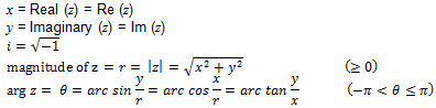
A complex number (z) is expressed in the form:
The properties of complex numbers and their ability to be expressed in Cartesian, polar or exponential form make them useful in solving equations that go beyond the limitations of the real number system. In hydroacoustics, a complex number can store the magnitude, frequency and phase of echoes where the transmit pulse is frequency modulated. References: |
|||||||||||||||||||||||||||
|
Schools analysis variables that are only available for export if the School Detection module is licensed. See: Schools Algorithms for more information. |
|||||||||||||||||||||||||||
|
The path of a ship or vessel over the water surface. A transducer installed with the major-axis aligned "across-track" means that the major-axis is perpendicular to the cruise track. When this alignment of the major-axis occurs, the major-axis 3 dB beam width may be used as an across-track beam width given that additional conditions are met. For more information refer to Beam angle parameters and related parameters in Echoview. See: Using Cruise tracks for more information. |
|||||||||||||||||||||||||||
|
Comma-separated values files - an text file format in which each complete value (e.g. a data value, name of an analysis variable) is separated by comma. The first line of a CSV file typically contains 'column headings' and each subsequent line contains the data values. The majority of exports in Echoview are written to CSV files. See: About file formats, Export file formats for more information. Note: Echoview will allow you to add CSV data files to a fileset if they meet certain criteria (see Text data files). |
|||||||||||||||||||||||||||
CUDA |
CUDA (Compute Unified Device Architecture) is a parallel computing platform and application programming interface (API) that allows software to use certain types of graphics processing units (GPUs) for general purpose processing. |
||||||||||||||||||||||||||
|
The projection of an echogram into a 3D scene allowing visualization of the relationships of echosounder pings to other 3D objects. |
|||||||||||||||||||||||||||
|
A self contained packet of information in a data file. See also: Telegram, tuple. |
|||||||||||||||||||||||||||
|
A single Sv or other variable value on an echogram. Single beam echogram data points are as samples. Single target echogram data points are single targets. See: About echograms for more information. |
|||||||||||||||||||||||||||
|
An area on an echogram where biomass within a beam is indistinguishable from the bottom echo (Kloser et al. 1996). See: About the deadzone for more information. |
|||||||||||||||||||||||||||
A technique in machine learning where "deep" refers to the hidden layers in the neural network. (See also artificial intelligence and supervised learning.) |
|||||||||||||||||||||||||||
|
Echoview supports the input of latitude and longitude in both decimal degree format and the degree and minute format. See: About degrees and minutes for more information. |
|||||||||||||||||||||||||||
|
Bottom or near bottom living species. |
|||||||||||||||||||||||||||
|
A computer programming term meaning an item or function is no longer used. |
|||||||||||||||||||||||||||
|
Linear distance from the water surface along the vertical axis. See: About depth, range and altitude and About single target depths for more information. |
|||||||||||||||||||||||||||
|
A regular grid of lines of constant depth or range displayed on the echogram. See: Grid page of the Variable properties dialog box for more information. |
|||||||||||||||||||||||||||
|
Dynamic Host Configuration Protocol server. DHCP servers allocate IP addresses dynamically so that addresses can be reused when hosts no longer need them. |
|||||||||||||||||||||||||||
|
Digital echogram data |
Digital data that can be used to display an echogram. |
||||||||||||||||||||||||||
|
The angular width, in degrees, of a beam as displayed on a multibeam sector plot. |
|||||||||||||||||||||||||||
|
Distance variable |
Variables that contain a time-series of measurements associated with distance traveled by a platform from an arbitrary zero point. Note: Only vessel log variables are currently supported. See: About variables for more information. |
||||||||||||||||||||||||||
|
A software protection device that attaches to the parallel or other port of a PC. Echoview Software uses HASP dongles for licensed users. See: Dongle installation for more information. |
|||||||||||||||||||||||||||
|
The depth of the center of the transducer face relative to the water surface. In Echoview this is the difference between depth and range for a downward pointing vertically oriented transducer. See: About draft for more information. |
|||||||||||||||||||||||||||
|
Draft correction was a calibration setting in older versions of Echoview. It was replaced by transducer geometry in Echoview 3. See: About draft for more information. |
|||||||||||||||||||||||||||
|
A dynamic-link library (DLL) is a file which can have an extension .dll, that can be loaded and executed by programs dynamically. |
|||||||||||||||||||||||||||
|
Distance in meters traveled or the angle of longitude measured eastward (positive or negative) from either a defined north-south grid line or a meridian. See: UTM zone for more information. |
|||||||||||||||||||||||||||
|
Acoustic back scatter data recorded for a particular echo or set of echoes. Used by Simrad to describe the echo of a single target as summarized in Ex500 echotrace (E) telegrams. See also: Bottom echo trace |
|||||||||||||||||||||||||||
|
Echocoastline |
A utility program that converts map files from formats that are not supported in Echoview to the .mif format. See: About Echocoastline for more information. |
||||||||||||||||||||||||||
|
An echogram is a standard method of displaying echosounder data. The Y (vertical) axis is used for depth, which increases towards the bottom of the screen. The X (horizontal) axis is used for time, which increases towards the right hand side of the screen. Individual points are color-coded to represent the strength of the returned signal at that time and depth. See: Echogram Display page of the Variable Properties dialog box for more information. |
|||||||||||||||||||||||||||
|
EchoListener |
A digital data logger (manufactured by SonarData) for logging data from single beam echosounders. |
||||||||||||||||||||||||||
|
Echolog 60 |
A program that reads, broadcasts and compresses Ex60 raw data files as they are being written. See: About Echolog 60 for more information. |
||||||||||||||||||||||||||
|
Echosim 60 |
EK60 simulator program distributed by Echoview Software for testing Echoview and Echolog 60. See: About Echosim 60 for more information. |
||||||||||||||||||||||||||
|
Echozip 60 |
A program for compressing raw data files that were logged from a Simrad Ex60. See: About Echozip 60 for more information. |
||||||||||||||||||||||||||
|
Echolog 80 |
A program that reads, broadcasts and compresses EK80 raw data files as they are being written. See: About Echolog 80 for more information. |
||||||||||||||||||||||||||
|
Echosim 80 |
EK90 simulator program distributed by Echoview Software for testing Echoview and Echolog 80. See: About Echosim 80 for more information. |
||||||||||||||||||||||||||
|
Echolog 500 |
A program that logs EK500 compatible telegrams being logged by a Simrad Ex500 or Ex60 echosounder. See: About Echolog 500 for more information. |
||||||||||||||||||||||||||
|
Echosim 500 |
EK500 simulator program distributed by Echoview Software for testing Echoview and Echolog 500. See: About Echosim 500 for more information. |
||||||||||||||||||||||||||
|
Old name for Echolog 500. See: About Echolog 500 for more information. |
|||||||||||||||||||||||||||
|
Echosim EK |
Old name for Echosim 500. See: About Echosim 500 for more information. |
||||||||||||||||||||||||||
|
An echosounder is a type of sonar where the acoustic beam has a fixed direction, generally 90 degrees to the surface (and towards the sea floor). Sound is transmitted by one or more transducers, and received signals are displayed on an echogram. Simple echosounders can be used to locate aggregations of fish and to determine the depth of the seabed. Scientific echosounders have electronics that are designed for (signal) stability and can offer processing functions for echo-integration (Sv data) and echo-counting. Types of echosounders.
See: Simmonds and MacLennan (2005): Chapter 3 Acoustic Instruments for more information. |
|||||||||||||||||||||||||||
|
The calibration constant of the echosounder. Used in Echoview only for EchoListener data. Other echosounders use specific names for their calibration constants (e.g. Transducer gain, Receiver sensitivity, Receiver gain ...). |
|||||||||||||||||||||||||||
|
The elementary distance sampling unit (EDSU) is the length of cruise track along which the acoustic measurements are averaged to give one sample. Definition from 8.7 The EDSU Simmonds and MacLennan 2005. |
|||||||||||||||||||||||||||
|
EK500 logger |
A program used to log data from a Simrad Ex500, e.g. Echolog 500. |
||||||||||||||||||||||||||
|
EK500 simulator |
See: Echosim 500. |
||||||||||||||||||||||||||
|
Obsolete name for the demonstration version of Echoview Software Echolog 500. Now called Echolog_500 demo.exe See: About Echolog_500 for more information. |
|||||||||||||||||||||||||||
|
Elevation is the angle between the beam axis and the vertical. See: About beam geometry and About transducer geometry for further information. |
|||||||||||||||||||||||||||
|
A file format that stores map data. In Echoview shapefiles can be viewed with cruise tracks. |
|||||||||||||||||||||||||||
|
An attribute file that stores pixel size and geographic positioning data for a corresponding raster image file. Supported ESRI world files include:
See: ESRI for more information. |
|||||||||||||||||||||||||||
|
A cylindrical equidistant projection, in which the horizontal coordinate is the longitude and the vertical coordinate is the latitude. Lines of longitude (meridians) are spaced closer together, forming rectangles with the lines of latitude (parallels) instead of squares. There are two standard parallels, resulting in less distortion at mid latitudes, but causing distortion at the Equator. |
|||||||||||||||||||||||||||
|
A synonym for Equivalent two-way beam angle. |
|||||||||||||||||||||||||||
|
Equivalent two-way solid beam angle |
Terminology used in Echoview 2.10 and previous. Now called Equivalent two-way beam angle. |
||||||||||||||||||||||||||
|
Equivalent two-way beam angle, Ψ (dB re 1 Steradian) ψ is the solid angle at the apex of the ideal beam, which would produce the same echo integral as the real transducer when targets are randomly distributed in space. ψ has units of Steradians. (MacLennan and Simmonds, 1992) Ψ = 10log(ψ) and has units of dB relative to one Steradian. |
|||||||||||||||||||||||||||
|
Ethernet |
A broadcast networking technology. All machines on one ethernet broadcast packets on the wire to all other machines, and each machine listens on the wire for packets addressed to it. Typically the TCP/IP protocol is used for communicating over Ethernets. |
||||||||||||||||||||||||||
|
A 48-bit number which uniquely identifies a network adapter. This number is hard-wired into the adapter hardware. It is usually represented with 12 hexadecimal digits, for example "00-00-01-00-a8-2a". Sometimes called the MAC address. |
|||||||||||||||||||||||||||
Ethernet telegrams |
EK500 compatible telegrams broadcast on an Ethernet by a Simrad Ex500 or Ex60 echosounder. |
||||||||||||||||||||||||||
|
Echoview file: a file used to organize echosounder data files into manageable units and to store the results of on-screen editing. See: About File sets for more information. |
|||||||||||||||||||||||||||
|
A collective term for the Simrad EA500, EK500 and EY500 echosounders. Exception: When used in relation to live viewing, Ex500 refers only to EK500 and EA500. |
|||||||||||||||||||||||||||
|
A collective term for the Simrad EK60, EA600, EA400 and EQ60, ES60 and EY60 echosounders. Exception: When used in relation to logging EK500 compatible telegrams, Ex60 refers only to EK60, EQ60, ES60 and EY60; the EA600/400 cannot log these types of data. |
|||||||||||||||||||||||||||
|
That line above which all data are ignored in an Echoview analysis, analysis export and data export. The exclude above line is selected on the Analysis page of the Variable Properties dialog box. Each variable may have its own exclude below line. It is typically used to exclude the near-field zone and transducer ring down often visible at the top of an echogram from the analysis. See also: Exclude below line. |
|||||||||||||||||||||||||||
|
Exclude below bottom |
Obsolete term from version 1. See: Exclude below line. |
||||||||||||||||||||||||||
|
A superceded analysis variable from pre 3.00 versions. Superceded by Exclude_below_line_depth_mean and Exclude_below_line_range_mean. |
|||||||||||||||||||||||||||
|
That line below which all data are ignored in an Echoview analysis, analysis export and data export. The exclude below line is selected on the Analysis page of the Variable Properties dialog box. Each variable may have its own exclude below line. It is typically used to exclude the bottom echo trace from the analyses. See also: Exclude above line. |
|||||||||||||||||||||||||||
|
Data that falls within an analysis domain, analysis export or data export but are excluded by either an exclude below line, an exclude above line or by bad line status. Note: This data is distinct from samples or regions that are affected by Analysis settings during analysis. |
|||||||||||||||||||||||||||
|
Exclude fixed surface layer |
Obsolete term from version 1. See: Exclude above line. |
||||||||||||||||||||||||||
|
The Exclude below and Exclude above lines. Data outside the exclusions lines (that is below the exclude below line or above the exclude above line) are excluded from all analyses. See About lines and About analysis domains for further information. |
|||||||||||||||||||||||||||
The Exchangeable image file format (Exif) is a standard that specifies formats for images and sounds recorded by digital instruments. The Exif specification generally adds metadata to existing file formats. |
|||||||||||||||||||||||||||
|
Export |
Export data to a data file (e.g. export underlying data or Sv data or analyses). |
||||||||||||||||||||||||||
|
A function which is used to define the opacity of 3D objects displayed in the Scene window over the scene time window. The fade function is selected on the Time Slider Properties dialog box from the Scene window. |
|||||||||||||||||||||||||||
|
Focus |
Can refer to either a window (see active window) or control. In either case the title bar will be highlighted and input from the keyboard will be received. |
||||||||||||||||||||||||||
|
Instrument scanning data is partitioned into frames to facilitate school detection. A frame represents a single scan of a volume of space (water). A frame is considered to be a single scan. See: About frames |
|||||||||||||||||||||||||||
|
The frequency of sound transmitted for a ping. This is a setting on the Calibration page of the Variable Properties dialog box for most acoustic variables. It is mainly intended for record keeping purposes. The Frequency Response graph and Ex60 Power to Sv and TS algorithm use this calibration setting. Wideband and pulse compressed wideband data may contain frequency response information that can be displayed in a Wideband frequency response graph. |
|||||||||||||||||||||||||||
|
The position of the point at the geometric center of an object - that is, the center of mass assuming the object has uniform density. This is a geometric property alone - compare with center of mass and centroid. |
|||||||||||||||||||||||||||
|
Information that is used to describe the position and size of objects in the real world. |
|||||||||||||||||||||||||||
|
A georeferenced image file based on the TIFF image format. GeoTIFF files share the same file extension as TIFF files (.tif, .tiff) but include additional header tags that store georeferencing information. See: GeoTIFF File Interpretation dialog box for more information. |
|||||||||||||||||||||||||||
|
Gray Level Co-occurrence Matrix. See: About the GLCM and textures for more information. |
|||||||||||||||||||||||||||
|
Data that falls within an analysis domain but are not excluded as bad data (no data), no data or excluded data. |
|||||||||||||||||||||||||||
|
Global Positioning System. |
|||||||||||||||||||||||||||
|
A measure of position at specific moment in time that was logged by a GPS receiver. Cruise tracks to which smoothing has not been applied are created from GPS fixes. Note: Echoview assigns a fix status to GPS fixes but does not alter the coordinates. |
|||||||||||||||||||||||||||
|
The quality status of the position (latitude and longitude) of a ping where the position was determined by interpolation from GPS fixes. See: About Cruise track for more information. |
|||||||||||||||||||||||||||
|
A division of echogram data into layers and intervals using depth/range grid lines and time/distance grid lines respectively. A grid is defined on the Grid page of the Variable Properties dialog box. |
|||||||||||||||||||||||||||
|
One of several possible ping modes used by scanning sonars. The multibeam echogram displays a 360 degree flat or conical beam fan (depending upon the tilt angle). Beam numbering is instrument specific. Refer to Echoview supported data file format details for your echosounder. An H-mode variable may be target-locked by specifying a partner V-mode variable. |
|||||||||||||||||||||||||||
|
A measure of the extent of an object (specifically a region, cell, region-cell intersection or selection), in the vertical direction. This term is used in depth mode. Thickness is the analogous term in range mode. See also: Thickness_mean and Height_mean. |
|||||||||||||||||||||||||||
|
The direction in which the fore-alongship axis of a platform is pointing. |
|||||||||||||||||||||||||||
|
Heave is the linear vertical (up/down) motion experienced by a platform (vessel). See also Heave: Degrees of freedom. In Echoview, heave data or altitude/depth sensor data may specified for the Heave source setting. For more information refer to About heave data and About heave compensation. |
|||||||||||||||||||||||||||
|
Hemisphere |
Northern or southern hemisphere of the earth. |
||||||||||||||||||||||||||
|
Hidden object |
Hidden object was terminology used prior to Echoview 4.40 for an unavailable object. From Echoview 4.40 on, a hidden object is an object (variable, transducer, platform or line) that is not displayed in the current view on the Dataflow window. |
||||||||||||||||||||||||||
|
Technique of using an echosounder, where the transducer points horizontally. Used especially in shallow waters such as rivers, lakes and reservoirs where a transducer pointing vertically (downwards) cannot sample effectively. In some cases the data from horizontal and vertical beaming can be combined to sample shallow and deep waters simultaneously. See: Horizontal beaming references for more information. |
|||||||||||||||||||||||||||
|
Hypertext Markup Language is a language for the creation of hypertext pages on the World Wide Web. See: http://www.w3.org/MarkUp/ for more information. |
|||||||||||||||||||||||||||
The ICES acoustic trawl survey database hosts information on fisheries observations collected from various pelagic surveys coordinated by ICES and falls into two categories: acoustic data, derived from readings taken on vessels, and biotic data, obtained through trawls in the pelagic zone. The database categories provide key biological data on fish stocks such as herring, mackerel and blue whiting as well as krill and other prey species. ICES data submitted: https://acoustic.ices.dk/submissions ICES vocabulary server for name codes: https://vocab.ices.dk/ ICES database validation rules: https://acoustic.ices.dk/validationrules See: Exporting ICES CSV data. |
|||||||||||||||||||||||||||
Image segmentation simplifies an image. It is a pixel-level process that clusters parts of the image into object classes. |
|||||||||||||||||||||||||||
|
Import |
An option on the File menu that is used to import region definition files (*.EVR), line definition files (*.EVL), HTI tracked echo files (*.ECH) or virtual variables into the current EV file. See: Importing in Echoview for more information. |
||||||||||||||||||||||||||
Refers to the trained model in machine learning usually in relation to supervised learning. Users input their data into the model, which then proceeds to search that data for any features it was trained to detect. |
|||||||||||||||||||||||||||
|
An inheritance chain is a flow of calibration settings from one variable to another through operand relationships. For example, take the variable relationship: A -> B -> C Where: A is a raw variable Virtual variables inherit their calibration settings from their first operand. Variable C obtains its Calibration source from variable B, while variable B obtains its Calibration Source from variable A. A Local supplement can be selected for any variable, but it is not inherited. See also: About virtual variables, Inheritance of properties. |
|||||||||||||||||||||||||||
|
A tree structure of variable operand relationships, rooted at a virtual variable of interest, which then branches through the variables operand relationships, up to the highest level of raw variables. |
|||||||||||||||||||||||||||
|
In Echoview, the display underneath an echogram that optionally reports ping status, mean Sv, maximum Sv or bottom classification on a per-ping basis. This definition is different from that found in Simmonds and MacLennan. The Simmonds and MacLennan definition for integram is similar to the Echoview integration line. See: Understanding echograms, About the integram and Using the integram for more information. |
|||||||||||||||||||||||||||
|
In Echoview this is a property sometimes held by a 3D point. For 3D points in a 3D polyline this will be the value of Intensity read from the .epl file when the polyline was imported. For 3D points in a 3D region track this will be the mean Sv of the 3D region the point represents. If the mean Sv could not be calculated at the time of detection this value will be -9.9e+37. See Integration from scenes for further information. |
|||||||||||||||||||||||||||
|
Calculation of the echo integral and other analysis variables. |
|||||||||||||||||||||||||||
|
Divisions on the time/distance axis of a grid, i.e. intervals are delineated by vertical bands on an echogram. See: About interval and layer values in export files for more information. |
|||||||||||||||||||||||||||
|
Internet protocol. The network protocol on which the Internet and many private networks are based on which the TCP and UDP protocols operate. |
|||||||||||||||||||||||||||
|
An address which uniquely identifies a computer using the Internet protocol. This address is usually specified as four decimal numbers separated by decimal points, e.g.: "192.168.1.102". |
|||||||||||||||||||||||||||
|
IP Port |
A number between 0 to 65535 used to establish individual connections on an IP networked machine. Datagrams on a network are addressed to a port at an IP, the complete address often written as: "192.168.1.102:80" for port 80 on the machine at 192.168.1.102:80. |
||||||||||||||||||||||||||
A numerical measure for the tails (outliers) of the distribution of a data set. When kurtosis is equal to three, the data has a normal distribution. A kurtosis greater than three means that the tails are heavier. A kurtosis less than three means the tails are lighter. Small set size adversely affects kurtosis. |
|||||||||||||||||||||||||||
|
Local area network. Typically a TCP/IP Ethernet. |
|||||||||||||||||||||||||||
|
LAN adapter number. Used internally by Microsoft operating systems to distinguish between multiple adapters on the same computer. |
|||||||||||||||||||||||||||
|
Latitude measures the north-south position of locations on the Earth's surface relative to a point found at the center of the Earth. Echoview supports the input of latitude and longitude in both decimal degree and degree and minute formats. Echoview accepts values between -89.9999 and +89.9999 decimal degrees for latitudes in the southern and northern hemisphere respectively. See: About degrees and minutes for more information. |
|||||||||||||||||||||||||||
|
Divisions on the depth/range axis of a grid, i.e. layers are delineated by horizontal bands on an echogram. See: About interval and layer values in export files for more information. |
|||||||||||||||||||||||||||
|
Layer Depth Lower - A superceded analysis variable from pre 3.00 versions. Superceded by Layer_depth_min and Layer_range_min. |
|||||||||||||||||||||||||||
|
Layer Depth Upper - A superceded analysis variable from pre 3.00 versions. Superceded by Layer_depth_max and Layer_range_max |
|||||||||||||||||||||||||||
|
A temporary line drawn on an echogram when creating or editing lines. It can be cleared at any time without affecting the lines in Echoview, or used to define a new editable line or modify an existing line (the active line). See Line and Surface tools and About lines for further information. |
|||||||||||||||||||||||||||
|
Left-right |
On HTI echosounders, the equivalent of Echoview's major-axis. |
||||||||||||||||||||||||||
|
“Method of storing a number so that the least significant byte appears first in the number. For example, given the hexadecimal number A02B, the little-endian method would cause the number to be stored as 2BA0. “ Reference: 2002, Microsoft Computer Dictionary Fifth Edition, Microsoft Press, Redmond Washington. |
|||||||||||||||||||||||||||
|
A calibration setting for variables derived from Simrad Q and E telegram data when data has been logged with an embedded transducer draft. See: Logged draft warning for more information. |
|||||||||||||||||||||||||||
|
Longitude measures the west-east position of locations on the Earth's surface relative to a circular arc called the Prime Meridian that is in-line with the location of the astronomical observatory at Greenwich, England. Echoview supports the input of latitude and longitude in both decimal degree and degree and minute formats. Echoview accepts values between -180.0000 and +180.0000 degrees for longitudes in the western (i.e. west of Greenwich) and eastern hemisphere respectively. See: About degrees and minutes for more information. |
|||||||||||||||||||||||||||
|
Longitudinal axis |
See: Alongship. |
||||||||||||||||||||||||||
|
Data compression where all information from the original file is preserved. |
|||||||||||||||||||||||||||
|
Lower display depth |
The deepest depth that can be displayed on an echogram. Set on the Echogram Display page of the Variable Properties dialog box. |
||||||||||||||||||||||||||
Machine learning is a sub-field of artifical intelligence where computer algorithms are developed to learn to recognize patterns in data. (See also artificial intelligence, deep learning and supervised learning.) |
|||||||||||||||||||||||||||
|
One of the two axes across the face of a transducer. The major-axis is typically the horizontal axis or the athwartship axis depending upon context (fixed platform or mobile platform). See: About beam geometry for details on specific manufacturer's preferred terminologies. |
|||||||||||||||||||||||||||
|
A format in which Echoview accepts maps for display on cruise tracks. See Map files. |
|||||||||||||||||||||||||||
|
Marker region |
A region whose purpose is to draw the operators attention to a section of the echogram. The region's name and annotation properties can be used to enter additional information. See: About regions for more information. |
||||||||||||||||||||||||||
|
A linear algebra manipulator and viewer package. |
|||||||||||||||||||||||||||
|
A superceded analysis variable from pre 3.00 versions. Superceded by Last_layer_depth_stop and Last_layer_range_stop. |
|||||||||||||||||||||||||||
|
Threshold applied to echogram data. |
|||||||||||||||||||||||||||
|
A superceded analysis variable from pre 3.00 versions. Superceded by Exclude_above_line_depth_mean and Exclude_above_line_range_mean |
|||||||||||||||||||||||||||
|
The median value in a list of values, is determined by sorting that list of values and choosing the value for which half the numbers are larger and half are smaller. The median of a list of 8 values would be half way between the 4th and 5th values in the sorted list. |
|||||||||||||||||||||||||||
|
A superceded analysis variable from pre 3.00 versions. Superceded by First layer_depth_start and First_layer_range_start. |
|||||||||||||||||||||||||||
|
One of the two axes across the face of a transducer. The minor-axis is typically the vertical axis or the alongship axis depending upon context (fixed platform or mobile platform). See: About beam geometry for details on specific manufacturer's preferred terminologies. |
|||||||||||||||||||||||||||
|
Minimum Sv is the weakest Sv value displayed with a color (i.e. not white) on the echogram. |
|||||||||||||||||||||||||||
|
A dialog box that requires a response e.g. click OK or Cancel. An application cannot continue until a response has been entered. |
|||||||||||||||||||||||||||
|
A term used in Echoview to refer to:
|
|||||||||||||||||||||||||||
|
A bathymetric export (.csv) of raw multibeam data (refer to Exporting multibeam bottom preview samples). | |||||||||||||||||||||||||||
|
A communications device that multiplexes (combines) several signals for transmission over a single medium. May be abbreviated to mux. |
|||||||||||||||||||||||||||
|
Common abbreviation for multiplexor. |
|||||||||||||||||||||||||||
|
The beam in a multibeam acoustic variable that is pointing vertically down or is closest to pointing vertically down. |
|||||||||||||||||||||||||||
|
Nautical area scattering coefficient sA (m2nmi-2).*
where:
Note: NASC was referred to as sA in Echoview 1.x. See: ABC and NASC for more information. *MacLennan et al 2002 Table 1. |
|||||||||||||||||||||||||||
|
National Marine Electronics Association. NMEA standards offer a combined electrical and data specification for communication between marine electronics such as echosounders, sonars, anemometers, autopilots, GPS receivers and other types of instruments. Echoview reads NMEA sentence data (e.g., RMA, RMB and RMC) and derives single source (single NMEA sentence) GPS and combined source GPS variables. Echoview 13 onward generates dedicated position variables (refer to Variable classes) for these NMEA sentences, and also adds them to position GPS fixes.
Echoview 13 onward generates position GPS fixes for NMEA sentences if they end in
Echoview support for NMEA sentence types may be detailed with your echosounder or sonar file format. If available, Echoview calculates a checksum from the contents of the NMEA sentence and compares it to the recorded checksum. |
|||||||||||||||||||||||||||
|
One point in a grid of similar points that Echoview creates for exporting region inspection data. This grid is configured on the Export region inspection data dialog box. |
|||||||||||||||||||||||||||
|
Noise power |
Background noise power is the power (dB re 1 Watt) present at the transducer due to background noise. Echoview now uses the Noise Sv at 1 m to specify the background noise level. |
||||||||||||||||||||||||||
|
A deprecated term in Echoview, which refers to beam width. |
|||||||||||||||||||||||||||
|
The measured pulse length divided by the PulseDuration yielding a normalized value, which is 1 when the measured pulse length is equal to the pulse duration. |
|||||||||||||||||||||||||||
|
Distance in meters traveled or the angle of longitude measured northward (positive or negative) from either a defined east-west grid line or a meridian. See: UTM zone for more information. |
|||||||||||||||||||||||||||
|
NTFS |
New Technology File System. The standard file system for Windows NT, 2000 and XP, replacing the FAT file system used in earlier versions. |
||||||||||||||||||||||||||
|
The Wavefront .obj file format is a standard 3D object file format. Obj files are text based files supporting both polygonal and free-form geometry (curves and surfaces). The color and materials of 3D object surfaces are stored in a related .mtl file. See: Supported features of .obj and .mtl files for more information. |
|||||||||||||||||||||||||||
|
Observed mean energy |
Synonym for Sv or Volume backscattering strength. |
||||||||||||||||||||||||||
|
A variable upon which an operator will act to produce a virtual variable. |
|||||||||||||||||||||||||||
|
A list of folders where the operating system looks for executable files if it is unable to find the file in the working directory. It is specified using the environment variable PATH. See Microsoft Windows help for information on how to modify this variable. |
|||||||||||||||||||||||||||
|
Phase data |
A synonym for angle data. |
||||||||||||||||||||||||||
|
A transmission of an acoustic pulse (a short burst of sound at the operating frequency of the sonar) from a transducer and the echo trace measured from that pulse (and the representation of that echo trace in Echoview). In Echoview, acoustic variables are made up of a series of pings. See also: About pings, pulse |
|||||||||||||||||||||||||||
|
In Echoview, the ping geometry is:
and, for multibeam pings also:
See: Using multiple operands for more information. |
|||||||||||||||||||||||||||
|
A property of each multibeam ping in Echoview, which defaults to 0. It has a value of 1 and 2 respectively for any two pings in a target-locked ping pair which do not have the exact same time. Otherwise it will be 0. It can be seen in multibeam data exports. |
|||||||||||||||||||||||||||
|
The pings in each variable in an EV file are sequentially numbered by Echoview, starting at 0. This is independent of any numbering those pings may or may not have in the data files from which they are read. |
|||||||||||||||||||||||||||
|
A status number associated with each ping. It can take one of 10 values which can be defined by the user on the Ping status page of the EV File Properties dialog box. It is selected for display on the Echogram Display page of the Variable Properties dialog box. See: About ping status and Understanding echograms for more information. |
|||||||||||||||||||||||||||
|
PIR is a superceded analysis variable from pre 3.0 versions. PIR was not replaced by a new variable. |
|||||||||||||||||||||||||||
|
Rotation of the platform (typically a vessel) about the Y axis (the athwartship axis). See: About pitch data for more information. |
|||||||||||||||||||||||||||
|
The basic unit of composition (picture cell) of a 2D image on a computer screen or similar display. This is analogous to the voxel for a 3D image. The intensity of a pixel is dependent on the display medium. For example: color intensity may be represented in three dimensions such as such Red, Green and Blue or gray scale intensity may be represented in gray level numbers. |
|||||||||||||||||||||||||||
|
A logical object in Echoview representing a fixed or moving structure from which data were logged. A moving platform has a position and heading which vary with time. Platform properties can be seen on the Position page of the Platform Properties dialog box. Echoview is able to account for the vertical moment of a platform by using data from a heave sensor or altitude sensor. The platform system reference point defines an X, Y, Z coordinate system for the relative placement of transducers, GPS antenna and the water level. See About transducer geometry for further information. The platform is represented by a shape on the Dataflow window. The platform is represented by the apex of a triangular outline on a 3D cruise track on the Scene window. See About Scene animation for more information. |
|||||||||||||||||||||||||||
|
The geographic location of a platform. The platform position is plotted as the location of the system reference point which is implicitly defined on the Position page of the Platform Properties dialog box. See: About transducer geometry for further information. |
|||||||||||||||||||||||||||
|
Pulse Length Determination Level. This defines how many decibels below the peak value of a detected pulse Echoview should consider when determining the pulse length during single target detection. See: Single target pulse properties for more information. |
|||||||||||||||||||||||||||
|
A program that was provided with Echoview 3.10 and earlier to convert Digital Chart of the World (DCW) map files into the .mif format. Pts2mif was superceded by Echocoastline. |
|||||||||||||||||||||||||||
|
The length (m) of a pulse (ping) in range space. The calculation for Pulse length is based on PulseDuration (ms) and SoundSpeed (ms-1). See also: Normalized pulse length, Transmitted pulse duration and Received pulse length. |
|||||||||||||||||||||||||||
|
On Simrad Ex500 series echosounders a setting of this name can take the value of Long, Medium or Short which must be specified on the Calibration page of Variable properties dialog box for the Power to Sv or TS calculation. Note: This setting is not required for data from a Simrad Ex60 series echosounder. See also Bandwidth. |
|||||||||||||||||||||||||||
|
A transmission of an acoustic pulse (a short burst of sound at the operating frequency of the sonar) from a transducer. See also: ping. |
|||||||||||||||||||||||||||
Pulse width |
In Echoview pulse width is referred to as Pulse length. |
||||||||||||||||||||||||||
|
Python is an interpreted high level language used for general programming. Python combines power with clear, readable syntax. It supports multiple programming paradigms, including object-oriented, imperative, functional and procedural, and has a large and comprehensive standard library. Echoview supports the Python NumPy and SciPy modules for use with the Code operator. NumPy and SciPy offer a wide range of open-source scientific computing and numerical integration capabilities. See also: https://www.python.org/, About the Code operator |
|||||||||||||||||||||||||||
|
Linear distance from the center of transducer face along the beam axis. See: About depth, range and altitude and About Range_Start and Range_Stop for more information. |
|||||||||||||||||||||||||||
|
A superceded analysis variable from pre 3.00 versions. Superceded by Target_range_max and Target_depth_max. |
|||||||||||||||||||||||||||
|
Range_mean |
An analysis variable representing the mean range of an object from the transducer face. In Pre 3.00 versions of Echoview this variable referred to the current variables Target_range_mean and Target_on_axis_depth_mean. With the introduction of a general range mode in version 3.00 these names changed. |
||||||||||||||||||||||||||
|
A superceded analysis variable from pre 3.00 versions. Superceded by Target_range_min and Target_depth_min. |
|||||||||||||||||||||||||||
|
An image that is defined as a collection of pixels arranged in a rectangular array of lines. The .jpg, .jpeg, .bmp, .png, .tiff, and .tif (including GeoTIFF files) are supported. See also: ESRI world files |
|||||||||||||||||||||||||||
|
A superceded term for underlying data in Echoview. No longer used, to avoid confusion with raw variables, data from files with the extension .raw and multibeam data which has not been beamformed. |
|||||||||||||||||||||||||||
|
The length (m) in range space of a backscattered pulse (ping) from a single target. Received pulse length is measured at a specified level below the peak value determined within the backscattered pulse. See also: Pulse length. |
|||||||||||||||||||||||||||
|
The beam in a multibeam acoustic variable that was used as the reference when calculating the calibration offset and two way beam angles. |
|||||||||||||||||||||||||||
|
A polygon displayed on the Echogram that is defined in time and depth coordinates. A region acts as a mask to select SV and TS data values that fall within its boundaries. There are several types of region: bad data region, analysis region and marker region. See: About regions for more information. |
|||||||||||||||||||||||||||
|
A property of Echoview regions. Classes are used for logical grouping of regions and are particularly useful for separating species and fish track detections. See: About region class for more information. |
|||||||||||||||||||||||||||
|
Region gridding is the process that takes ping data and generates calculated data points on a 3D grid of nodes. This takes place when exporting region inspection data. See: Region gridding algorithms for more information. |
|||||||||||||||||||||||||||
|
Region properties |
Properties of a region (e.g. name, type, class). See: About regions for more information. |
||||||||||||||||||||||||||
|
Rotation of the platform (typically a vessel) about the X axis (the alongship axis). See: About roll data for more information. |
|||||||||||||||||||||||||||
|
Rotation is the angle between the positive minor-axis of the transducer and the vertical plane running through the beam axis. See: About beam geometry and About transducer geometry for further information. |
|||||||||||||||||||||||||||
|
Router |
A device used to partition a network into subnets. |
||||||||||||||||||||||||||
|
One of several possible ping modes used by scanning sonars. The multibeam echogram displays a flat beam fan which may have bearing or tilt angles applied. Beam details are instrument specific. Refer to Echoview supported data file format details for your echosounder. |
|||||||||||||||||||||||||||
|
Symbol commonly used by Simrad to represent NASC. |
|||||||||||||||||||||||||||
|
Sa correction is determined during the calibration process of some Simrad echosounders. The value represents the correction required to the Sv constant to harmonize the TS and Sa (NASC) measurements. Sa corrections are only determined during a calibration, otherwise they are zero. Consult the Simrad Ex60 or EK80 Help file for more details. SaCorrectionFactor can be entered on the Calibration page of the Variable Properties dialog box. |
|||||||||||||||||||||||||||
|
An echogram data point: a single Sv or other variable value. See: About echograms for more information. |
|||||||||||||||||||||||||||
|
For samples in a multibeam variable, the angle of the beam (in which the sample is located) to the transducer axis. |
|||||||||||||||||||||||||||
|
A synonym for Sample thickness. Note: Strictly the sample thickness is only a sample height for downward pointing vertically oriented transducers. |
|||||||||||||||||||||||||||
|
The thickness of one sample on an echogram (m). This may be calculated as the range of data collection divided by the number of samples collected. If 500 samples are collected over a range of 1000m for example, the sample thickness would be 2m, but if 500 samples are collected over a range of 100 meters, the sample thickness would be 20 cm. It may also be calculated as half the sound speed divided by the sampling frequency. See: About start and stop ranges for further examples. |
|||||||||||||||||||||||||||
|
A measure of the physical volume that a sample is considered to occupy. This is generally defined ins such a way that a body of water can be divided into contiguous sample volumes. One dimension of the sample volume will typically be the sample thickness for example. This is an important measure in estimating the biomass density. Note: This is distinctly different to the sampling volume and typically smaller (because the digital sampling rate is typically such that there are several samples taken in a pulse length). |
|||||||||||||||||||||||||||
|
The frequency at which digital samples are taken from an analog signal. The sampling frequency is equal to half the sound speed divided by the sample thickness. |
|||||||||||||||||||||||||||
|
A measure of the physical volume that has contributed information to the value represented by a sample. This is typically a function of the pulse length and beam width. One dimension of the sampling volume will typically be half the pulse length, customarily expressed as cτ/2 (where c is the sound speed, and τ the pulse duration). This is an important measure in the estimation of Sv from measured signal strength (see for example the TS to Sv operator). Note: This is distinctly different to the sample volume and typically larger (because the digital sampling rate is typically such that one pulse length contains several samples). |
|||||||||||||||||||||||||||
|
A scan in Echoview is defined as follows:
See: About scanning |
|||||||||||||||||||||||||||
|
The scene finish time is the end of the scene time window and can be modified using the Finish time slider on the Time slider of the Scene window. |
|||||||||||||||||||||||||||
|
The scene start time is the start of the scene time window and can be modified using the Start time slider on the Time slider of the Scene window. |
|||||||||||||||||||||||||||
|
The current time, or now, for a scene. If a scene displays a moving platform, the scene time determines where that platform is. The scene time is equal to the scene finish time. That is to say, the scene time window is looking into the past only. |
|||||||||||||||||||||||||||
|
The scene time window can be adjusted using the Time slider of the Scene window, only within the scene time limits. Ordinarily the scene time limits cover the valid times of all 3D objects in the scene. You can set them manually on the Time Slider properties dialog box however. |
|||||||||||||||||||||||||||
|
The window of time between the scene start time and the scene finish time. All of the 3D objects in a scene which have a valid time overlapping the scene time window will be visible in the scene. Those which have a valid time outside of the scene time window will not be visible. |
|||||||||||||||||||||||||||
|
Generic term for any on-screen tip that appears when the mouse points to an object. See also: Tooltip |
|||||||||||||||||||||||||||
|
The sum of the beam widths of all beams in a multibeam acoustic variable. |
|||||||||||||||||||||||||||
|
Selection |
A section of the current window defined using the mouse. It is usually indicated by a solid gray border. Many menu commands implicitly operate on the current selection. |
||||||||||||||||||||||||||
|
Shadow zone |
A synonym for deadzone. |
||||||||||||||||||||||||||
|
SHAPES (shoal analysis and patch estimation system) is a Sea Fisheries Research Institute (SFRI)-developed software capable of detecting, extracting and statistically characterizing fish schools in an automated and objective manner from acoustic data. Echoview implements some of the SHAPES algorithms. |
|||||||||||||||||||||||||||
|
Shortcut menu |
A menu displayed when the secondary (usually the right) mouse button is pressed. The contents of the menu will change according to the current program state (context). This is sometimes referred to as the context menu. |
||||||||||||||||||||||||||
|
A term used in Echoview to refer to:
|
|||||||||||||||||||||||||||
|
Single ping echogram data |
High depth resolution digital backscattering strength data logged from every ping of an echosounder and used to display digital echograms. Compare to integrated data, which is backscattering strength data integrated in depth/distance cells using an echo integrator before logging. |
||||||||||||||||||||||||||
A numerical measure for symmetry of the tails of the distribution of a data set. When skewness is equal to zero, the data has a normal distribution. Skewness indicates the direction of deviation from the mean. Positive skewness means the left tail is shorter than the right tail and the distribution is skewed to the right. Negative skewness means that the left tail is longer than the right tail and the distribution is skewed to the left. Small set size adversely affects skewness. |
|||||||||||||||||||||||||||
|
A stand-alone GPS data smoothing program that was developed and distributed (on request) by SonarData for use with Echoview 3.10 and earlier. GPS smoothing can now be done in Echoview and Smoothie is no longer distributed. |
|||||||||||||||||||||||||||
|
This is the abbreviation for signal to noise ratio. SNR is a measure of signal strength relative to background noise. The ratio is usually measured in decibels (dB).
|
|||||||||||||||||||||||||||
|
A sonar device is one that uses sound for the detection and observation of objects in water. There are two types of sonar: active and passive. Passive sonar uses a receiver to interpret received signals. Active sonar uses a transducer to transmit and receive signals, which are then interpreted on an echogram. The acoustic beam or beams of a sonar can be oriented in any direction by rotation, a pan or a tilt. An echosounder is a particular type of sonar. See: Simmonds and MacLennan (2005): Chapter 3 Acoustic Instruments for more information. |
|||||||||||||||||||||||||||
|
SonarData Echolog EK |
Old name for Echolog_500. |
||||||||||||||||||||||||||
|
Speed of sound in water in m/s. See: Calibration page of Variable properties dialog box for more information. |
|||||||||||||||||||||||||||
|
Point backscattering strength data logged with Simrad ER60 software. Known as TS in Echoview. For such data, Simrad now define TS as the subset of Sp data that has been confirmed (via single target detection) to correspond to a single target. |
|||||||||||||||||||||||||||
|
Echoview can apportion backscatter signal to a pre-defined mix of species for the purpose of biomass estimation. See About species for further information. |
|||||||||||||||||||||||||||
|
The spherical scattering cross-section, denoted by σsp. Spherical scattering cross-section in m2 is defined* by:
*MacLennan et al 2002 Table 1. |
|||||||||||||||||||||||||||
|
The smallest executable entity within a programming language. Source: Microsoft Corporation (2002). Microsoft Computer Dictionary - 5th edition. Microsoft Press. |
|||||||||||||||||||||||||||
|
A portion of a network that is partitioned by a router. |
|||||||||||||||||||||||||||
|
The process of training an inference model from a repository of examples that instruct the model what to identify. (See also artificial intelligence, deep learning and machine learning.) |
|||||||||||||||||||||||||||
|
Sv (dB re 1 m-1) is defined as the (Mean) Volume backscattering strength (MVBS)*. See also: Sv mean algorithm.
where:
*MacLennan et al 2002 Table 1. |
|||||||||||||||||||||||||||
|
An Echoview calibration setting that is applied to Simrad Ex500 telegrams. This setting corresponds with the Sv Transd. Gain setting on an Ex500 echosounder's Transceiver menu and is defined in the Simrad EK500 Operator Manual as "Peak transducer gain for computation of back scattering strength." |
|||||||||||||||||||||||||||
A multibeam swath or swathe is the combination of transmit and receive beams arising from a configured array of transducer elements. Some elements transmit a composite beam and some elements are used to electronically form multiple perpendicular receive beams. See also Demer et al (2015) Calibration of acoustic instruments: Section 1.3.4 Multibeam. |
|||||||||||||||||||||||||||
|
The grammar of a language; the rules governing the structure and content of statements. Source: Microsoft Corporation (2002). Microsoft Computer Dictionary - 5th edition. Microsoft Press. |
|||||||||||||||||||||||||||
|
A property of Echoview (multibeam) targets. Target classes are used to classify targets and are particularly useful for discriminating target data in exported .csv files during post-processing. Target classes are stored and managed in the Target Metadata window. |
|||||||||||||||||||||||||||
|
It is possible for some scanning sonars to produce an H-mode and a V-mode ping, which pass horizontally and vertically through one school of fish. Two such pings are considered target-locked, and Echoview provides algorithms for detecting schools from such a ping pair (extrapolating from the data a three dimensional region) and integrate the data from such a ping pair (also extrapolating from sampled data). |
|||||||||||||||||||||||||||
|
Target strength* (TS in dB re 1m2) is the logarithmic form of the backscattering cross-section. Target strength is calculated from echo intensity using a point source model for the sonar equation. The calculated values may be displayed in Echoview as a TS echogram.
where:
Target strength values in single target detection variables may have compensation for the beam pattern applied, see compensated TS and uncompensated TS for more information. Target strength is commonly abbreviated in Echoview as TS. Note: In situ TS estimation may be used to provide a species TS value for biomass estimation. Outputs from the Cell statistic operator may be used to apply confidence limits (density index) to in situ TS estimation. *MacLennan et al 2002 Table 1. |
|||||||||||||||||||||||||||
|
Transmission Control Protocol. A connection-oriented network protocol that operates on top of the Internet protocol. Echoview does not use this protocol directly. An alternative to UDP. |
|||||||||||||||||||||||||||
|
Transmission Control Protocol/Internet Protocol. In practice it is usually used to describe an implementation of TCP, IP and UDP. |
|||||||||||||||||||||||||||
|
A block of data output by a Simrad echosounder on its serial port or Ethernet port. A telegram always contains a time and a telegram type, and may contain other data (e.g. Sv values, TS values, raw power) depending on the telegram type. ek5, .dgn, .dg and BI500 data files are essentially a sequence of telegrams. See also: Datagram |
|||||||||||||||||||||||||||
|
A measure of the extent of an object (specifically a region, cell, region-cell intersection or selection), along the beam axis. This term is used in range mode. Height is the analogous term in depth mode. See also: Thickness_mean and Height_mean |
|||||||||||||||||||||||||||
|
A value on the Data page of the Variable Properties dialog box that is used in calculating the single target display thickness. Supported values may be determined by the echosounder that logged the data or by the operands used for the single target detection. See: Configuring single target display thickness for more information. |
|||||||||||||||||||||||||||
|
An raster image file format. TIFF (Tagged Image File Format) files may have a .tif or .tiff file extension. TIFF files containing a DEM (digital elevation model) are not supported. See also: GeoTIFF |
|||||||||||||||||||||||||||
|
A term used for scanning sonar systems to describe the angle of a beam fan from the horizontal. Tilt angles range from -10 to 90 degrees. Zero degree tilt is defined as horizontal and 90 degree tilt as vertical downwards - negative tilt is above the horizontal. See your echosounder details for further information. Tilt applies to H-mode and S-mode beams only. |
|||||||||||||||||||||||||||
|
A feature on the scene window to enable scene animation. |
|||||||||||||||||||||||||||
|
A grid of vertical lines drawn on the echogram where the spacing between the lines (grid spacing) is defined in terms of time, distance or ping count. See: Grid page of the Variable properties dialog box for more information. |
|||||||||||||||||||||||||||
|
Data can be thresholded using a threshold function (TVT or time-varied threshold) that is dependent on range from the transducer, where the function of range is of the same form as a "20log(r)" time-varied gain (TVG) function. |
|||||||||||||||||||||||||||
|
A tooltip is a descriptive text box for a feature on the screen. It appears when the mouse pointer is held over a tool, button or other object. See also: ScreenTip |
|||||||||||||||||||||||||||
|
The transmit/receive calibration constant in dB for an instrument system. The TR Factor is commonly used in power to Sv or power to TS equations. |
|||||||||||||||||||||||||||
|
Transceiver |
The transmitter and receiver electronics of an echosounder or other instrument. |
||||||||||||||||||||||||||
|
A transducer on a fisheries echosounder converts electrical energy into the transmitted acoustic pulse (or "ping") and converts the received acoustic echoes back into electrical signals for further processing in the echosounder. In Echoview a transducer is a logical object in the software that represents a physical transducer or a data acquisition device. A transducer is mounted on a platform, at a location, with an orientation. Every variable in Echoview is associated with one and only one transducer, but one transducer may be associated with more than one variable. You can create new transducers on the Dataflow window. Transducer properties can be seen on the Transducer properties dialog box. Echoview can create a virtual line based on the near-field depth of the transducer; the near-field zone may be unsuitable for calibration sphere or analysis calculations. |
|||||||||||||||||||||||||||
|
The axis beginning at the center of the transducer face and extending in the direction in which the transducer is pointing. A synonym for central axis. |
|||||||||||||||||||||||||||
|
A setting that can be entered on the Transceiver menu of Simrad EK500 and EY500 echosounders, representing the draft of the transducer. It influences Q and E telegrams and results in a logged draft on Sv, TS and single target echograms. We recommend you set this value to 0 in your echosounder. See also: Logged draft warning. |
|||||||||||||||||||||||||||
|
An Echoview calibration setting that is applied to Simrad Ex60 raw data. This setting corresponds with the Gain setting on the Ex60's Advanced Transceiver dialog box and is defined in the Simrad EK60 Instruction Manual as "The transducer gain presented by calculating the directivity multiplied by the transducer's efficiency." Note: The value used during logging is available under Ping (from file) on the Details dialog box (F9). |
|||||||||||||||||||||||||||
|
The power output of the echosounder in Watts. See About calibration settings. |
|||||||||||||||||||||||||||
|
Also known as pulse duration. The duration in milliseconds of an individual pulse (ping) transmitted by a transducer. See also: Pulse length and About transmitted pulse. |
|||||||||||||||||||||||||||
|
Transversal |
A synonym for athwartship. |
||||||||||||||||||||||||||
|
Abbreviation for target strength. See also: Sp |
|||||||||||||||||||||||||||
|
An Echoview calibration setting that is applied to Ex500 compatible telegrams. This setting corresponds with the TS Transd. Gain setting on an Ex500 echosounder's Transceiver menu and is defined in the Simrad EK500 Operator Manual as "Peak transducer gain for computation of target strength." |
|||||||||||||||||||||||||||
|
A synonym for Equivalent two-way beam angle. |
|||||||||||||||||||||||||||
|
A single record in a HAC or DT4 file. A tuple contains a tuple type and length, and additional data depending on the type. See: BioSonics data files and HAC data files for more information. |
|||||||||||||||||||||||||||
|
Time-Varied Gain. A range based function which serves to correct for losses due to absorption and beam spreading, for example, TVG(r) = 20*log(r)+2*a*r, where r is the range from the transducer face to the sample. For more information refer to About time varied gain. |
|||||||||||||||||||||||||||
|
This is the coefficient of the log(r) term in the TVG equation. The value is recorded by some echosounder manufacturers in their data files (RESON, Kongsberg and Simrad) as the "TVG spread/4", "TvgAFactor" or "TVG". In Echoview Data generator algorithms the TVG range coefficient can take typical values or can be user specified. |
|||||||||||||||||||||||||||
|
User Datagram Protocol. A connection less network protocol that doesn't guarantee the delivery or ordering of data, but has low start-up overhead. An alternative to TCP. |
|||||||||||||||||||||||||||
|
A line in Echoview which is generally unavailable for use, but for which the properties are retained (and stored in an EV file). A line is unavailable if:
Unavailable objects are of particular importance to the functioning of EV file templates. |
|||||||||||||||||||||||||||
|
A variable or line in Echoview which is generally unavailable for use, but for which the properties are retained (and stored in an EV file). Prior to Echoview 4.40, an unavailable object was called a hidden object. Some unavailable objects or unavailable virtual variables can be displayed on the Dataflow window. See Unavailable variable and unavailable line. |
|||||||||||||||||||||||||||
|
A variable in Echoview which is generally unavailable for use, but for which the properties are retained (and stored in an EV file). A variable is unavailable if:
Unavailable objects are of particular importance to the functioning of EV file templates. Notes:
|
|||||||||||||||||||||||||||
|
Universal naming convention. A Microsoft standard for specifying file locations on a network. Each name follows the general form: \\Computer\Share\Path\FileName.Ext, where "Computer" is the computer name on which the file is located, "Share" is the share name, path is the (optional) path relative to the shared folder and "FileName.Ext" is the name of the file. E.g.: "\\MyServer\Ek500Data\Jan97\19970101-0001.ek5". |
|||||||||||||||||||||||||||
|
Target strength derived from received power signals without beam compensation applied. This is available in the analysis variable TS_uncomp. See also: Compensated TS. |
|||||||||||||||||||||||||||
|
Data values logged by an echosounder. Underlying data values are different for each type of data file. For example, EchoListener data files store a single 12-bit analog-to-digital converter (ADC) value, Simrad files store a 16-bit encoded EK number, BioSonics data files store an encoded amplitude count. Echoview derives variables from underlying data, e.g. Echoview may derive an Sv variable from underlying power data or underlying Sv data. See: Exporting data for information about exporting underlying data. |
|||||||||||||||||||||||||||
|
The point in time corresponding to 01 January 1970 at 00:00, and commonly adopted as a reference in computing. |
|||||||||||||||||||||||||||
|
Data to which:
See: Calibrated data for more information. |
|||||||||||||||||||||||||||
|
Universal Time Coordinates. Time system used with GPS information. Close to, but not exactly the same as GMT (Greenwich Mean Time). See About Cruise track. |
|||||||||||||||||||||||||||
|
Universal Transverse Mercator Projection: a conformal projection with parameters chosen to minimize distortion over a defined set of small areas (UTM zones). It is not equal area, equidistant, or perspective. |
|||||||||||||||||||||||||||
|
The UTM system divides the world's surface into 60 six-degree (of longitude) wide zones that run north-south, starting at the International Date Line. They are successively numbered in an eastward direction. Each zone stretches from 84° North to 80° South. Location is measured in these zones from a reference point which is at the intersection of the equator and the central meridian for each zone. Coordinate measurements of location are made relative to this point in meters in eastings (longitudinal distance) and northings (latitudinal distance). |
|||||||||||||||||||||||||||
|
Up-down |
On HTI echosounders, the equivalent of Echoview's minor-axis. |
||||||||||||||||||||||||||
|
Upper display depth |
The shallowest depth displayed in an echogram. Set on the Echogram Display page of the Variable properties dialog box. |
||||||||||||||||||||||||||
|
One of several possible ping modes used by scanning sonars. The multibeam echogram displays a flat beam fan which may have a bearing angle applied. Beam details are instrument specific. Refer to Echoview supported data file format details for your echosounder. A V-mode variable may be target-locked by specifying a partner H-mode variable. |
|||||||||||||||||||||||||||
|
The end of the valid time range for a 3D object. |
|||||||||||||||||||||||||||
|
The start of the valid time range for a 3D object. |
|||||||||||||||||||||||||||
|
A property of 3D objects which defines the time over which an object is considered to validly exist. An object may have a single valid time, or a range of valid times (from a start time to a finish time). The valid time is used in conjunction with the scene time window and a fade function to determine the opacity of an object when it is displayed in the Scene window. It is also used in determine whether objects intersect with ping data or not. The valid time is set on the Time page of the (3D Object) Properties dialog box. See: About scene animation. |
|||||||||||||||||||||||||||
|
A time-series of measurements of one data type. Echoview uses variables to organize source data (e.g. data files from an echosounder) for display, analysis, export, etc. purposes. See: About variables for more information. |
|||||||||||||||||||||||||||
|
The data made available by a variable. This is distinct from underlying data, which is found in data files. Echoview may apply calibration settings or other calculations to underlying data, as required, to produce variable data. |
|||||||||||||||||||||||||||
|
"...In a virtual memory system, the address that the application uses to reference memory. The memory management unit (MMU) translates this address into a physical address before the memory is actually read or written to. ..." Excerpt from Microsoft Corporation (2002). Microsoft Computer Dictionary - 5th edition. Microsoft Press. |
|||||||||||||||||||||||||||
|
A virtual echogram is an echogram based on a virtual variable. |
|||||||||||||||||||||||||||
|
"...Memory that appears to an application to be larger and more uniform than it is. Virtual memory may be partially simulated by secondary storage such as a hard disk. Applications access memory through virtual addresses, which are translated (mapped) by special hardware and software onto physical addresses. ..." Excerpt from Microsoft Corporation (2002). Microsoft Computer Dictionary - 5th edition. Microsoft Press. |
|||||||||||||||||||||||||||
|
Virtual variable |
A variable in Echoview created from one or more other variables using an operator (mathematical algorithm). See: About virtual variables for more information. |
||||||||||||||||||||||||||
|
Visual Analyzer |
A BioSonics software package for analyzing .DT4 data files. |
||||||||||||||||||||||||||
|
sv is defined as the volume backscattering coefficient* (m-1). See also: Sv, Sv mean algorithm.
where:
*MacLennan et al 2002 Table 1. |
|||||||||||||||||||||||||||
|
Refer to Sv. |
|||||||||||||||||||||||||||
|
Volume_sampled is a superceded analysis variable from pre 3.10 versions. It has been superceded by beam_volume_sum. |
|||||||||||||||||||||||||||
|
A voxel is a volume cell, representing a value in three dimensional space. This is analogous to a pixel (picture cell), which represents 2D image data. Voxels are frequently used in the visualization and analysis of medical and scientific data. There are two interpretations for a voxel value, depending on usage:
When exporting region inspection data, Echoview defines a grid of nodes and calculates an intensity for each node using a specified algorithm. See: https://en.wikipedia.org/wiki/Voxel for more information about voxels. |
|||||||||||||||||||||||||||
|
Virtual Reality Modeling Language. VRML files define worlds, which can represent 3D computer-generated graphics, 3D sound, and hypermedia links. VRML is useful for visualization of scientific data. |
|||||||||||||||||||||||||||
|
The operating wavelength of the echosounder in meters. Can be obtained by dividing the sound speed in meters/second by the frequency in Hz. Note:
|
|||||||||||||||||||||||||||
|
"... A Web Map Service (WMS) is a standard protocol for serving georeferenced map images over the Internet that are generated by a map server using data from a (Geographic Information System) GIS database. ..." Excerpt from Wikipedia Web Map Service page. See: Adding a WMS map to a cruise track window and About WMS maps. |
|||||||||||||||||||||||||||
|
The windows displayed by Echoview, their positions and contents. This can be saved so that it is restored whenever you open an EV file, and the same window layout is presented. The workspace is stored independently for each EV file, in a file in the same folder and of the same name with the .evwx extension. For example the workspace for the EV file Example.EV is stored in the file Example.evwx. If this file is deleted, moved or renamed then Echoview will not restore the workspace for Example.EV when it is opened. See EV File page of the EV File Properties dialog box for further information. |
|||||||||||||||||||||||||||
|
File extension for the VRML world file format. Scenes and 3D objects can be exported in this format and viewed as a 3D world in a VRML viewer. .wrl files are written as text data files and can be viewed in their raw state using a text editor. |
|||||||||||||||||||||||||||
|
An earth fixed global reference frame that defines the shape of an earth ellipsoid, its angular velocity, the earth mass which is included in the ellipsoid reference, and a gravity model of the earth. |
|||||||||||||||||||||||||||
|
Extensible Markup Language (XML) defines a set of rules for encoding documents in a format that is both human-readable and machine-readable. |