Bottom_roughness_normalized
Bottom_roughness_normalized (dB re 1m2/m3) is a bottom feature that may be extracted during bottom classification. A Bottom_roughness_normalized analysis variable can be selected under Bottom on the Export page of the EV File Properties dialog box. It can be included with onscreen analyses and exported. Within a data set, roughness values are relative to each other. A higher roughness corresponds to a rougher substrate.
Bottom_roughness_normalized represents the mean of the depth normalized roughness index E1 in the Feature extraction interval for a bottom classification.
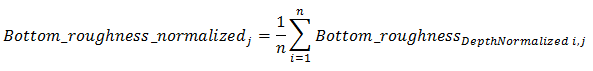
where:
Siwabessy et al (1999) discuss the quantities E1 and E2.
E1 is known as a roughness index. E2 is known as a hardness index.
The following is an excerpt from their paper:
“…E1 is derived from an integration of the tail of the first acoustic bottom return and E2 is derived from an integration of the complete second acoustic bottom return. The rationale of this is that the energy in the tail of the first acoustic bottom returns (E1) arises from the roughness of the seabed and that of the entire second acoustic bottom returns (E2) arises from the acoustic impedance mismatch of the seabed and the water column (Chivers et al., 1990; Chivers and Burns, 1992). This parameter is customarily taken to represent the “hardness” of the seabed. Heald and Pace (1996) provide theoretical expressions derived from scattering theory for E1 and E2. …”
Echoview uses a variation of Equation (1) from Siwabessy et al (1999) to determine E1 for the first bottom echo of the pings in the Feature extraction interval.
Extent of the first bottom echo
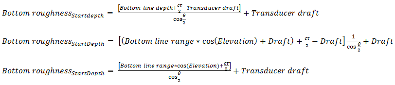
The start and end of roughness index calculations for the first bottom echo is given by:

c
=
Speed (m/s) of sound in the medium.
τ
=
Pulse duration (s)
θ
=
3dB beam angle
Transducer draft
=
Transducer draft is specified as Z-vertical offset on the Geometry page of the Transducer Properties dialog box.
Bottom line depth
=
Bottom line depth (m) at the first bottom echo at ping p.
Depth = Range x cos(Elevation) + Transducer draftBottom line range
=
Bottom line range (m) at the first bottom echo at ping p.
Bottom echo threshold value (1m)
=
Bottom echo threshold value (1m) under Bottom on the Analysis page of the Variable Properties dialog box.
j
=
Bottom point in a bottom points variable.
Bottom point number j is assigned sequentially in time. The pings of the echogram are partitioned according to the number of pings in a specified Feature extraction interval.
i
=
Ping i in the Feature extraction interval j.
k
=
Sample k of the first bottom echo in Ping i in the Feature extraction interval j.
See also Extent of the first bottom echo.
n
=
Number of pings in Feature extraction interval j.
m
=
Number of samples in the first bottom echo of ping i.
See also Extent of the first bottom echo.
Bottom_roughnessDepth normalized i,j
=
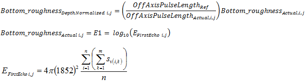
Depth normalized roughness index for ping i in Feature extraction interval j.
The depth normalization equation is:
Refer to depth normalization algorithms for definitions of OffAxisPulseLengthRef, OffAxisPulseLengthActual.
EFirstEcho i, j
=
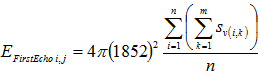
Roughness index E1 for ping i in Feature extraction interval j.
where:
sv(i, k) is the linear value for Sv for sample k in ping i.
Notes:
The roughness index set of samples is a limited to samples that occur in a defined part of the first bottom echo.
Hamilton 2001 observes that although E1 is treated as a roughness index, it may also been seen as a bottom backscatter index which has components of roughness and hardness (p 11).

See also
About bottom classification
Bottom classification algorithms
EV File Properties dialog box