Target Samples Bitmap
This operator creates a bitmap variable (boolean) with the same ping geometry as the first operand. Two methods are offered. The output bitmap is created with the ping geometry of the first operand and boolean values based on a method's single target sample definition applied to the second operand. See also Wideband frequency response considerations.
Echoview accepts operands of the following data types as input:
|
Operand 1 |
Operand 2 |
|
|
Settings
The Target Samples Bitmap Variable Properties dialog box pages include (common) Variable Properties pages and these operator pages:
Operands page
Target Samples Bitmap page
|
Setting |
Description |
Select samples using |
The Select samples using list includes:
Select Displayed target to create a bitmap for the set of samples corresponding to single targets and their single target display thickness. Select Transmitted pulse length or Target PLDL/6dB/12dB/18dB to create a bitmap for the set of samples that are used to calculate the single target. Target PLDL is the PLDL value read from the single target detection variable. The single target sample set is determined by the single target range, nominal peak TS and the normalized target pulse length at the Transmitted pulse length, PLDL or 6dB/12dB/18dB normalized pulse length determination levels. See also Single target pulse properties: Pulse length and pulse start and Characteristics of a single target peak envelope. |
|
Near margin |
The Near margin (m) adjusts the lowest sample range of the Select samples using sample set. See Figure 1. |
Far margin |
The Far margin (m) adjusts the highest sample range of the Select samples using sample set. See Figure 1. |
Algorithm
The output data point values are false when samples on a ping in the first operand fall outside a specified single target range. The following expressions describe the acceptable range for samples.
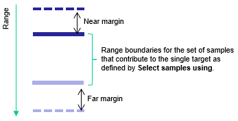
Figure 1. Schematic in range space shows the Target samples bitmap for a single target. Range values increase with distance from the transducer.
Near margin and Far Margin are specified on the Target Samples Bitmap page.
Select samples using: Displayed target
The bitmap is based on displayed targets from the single target echogram, adjusted by the values for Near margin and Far margin.
Bitmap upper limit = Single target range - Near margin
Bitmap lower limit = Single target range + Display thickness + Far margin
Where:
Single target range is taken from operand 2.
Display thickness is the single target display thickness and may not correlate directly to the samples that are used to generate the single target. You can configure the single target display thickness by changing the appropriate settings on the Data page of the Variable Properties dialog box.
Select samples using: Target PLDL/6dB/12dB/18dB
The bitmap is based on the samples that contribute to the single target sample envelope as specified under Select samples using and then adjusted by the values for Near margin and Far margin. The assumption is that the target peak is symmetrical/well formed. When the target envelope is not symmetrical/well formed some contributing samples may be missed. This method may be useful in analyses of calculations associated with Calibrating an echosounder.
Bitmap upper limit = [Target Peak Range - (TargetThicknessTargetLevel/2)] - Near margin
Bitmap lower limit = [Target Peak Range + (TargetThicknessTargetLevel/2)] + Far margin
Where:
c is the SoundSpeed (m/s) from the single target variable.
TargetThicknessTargetLevel = Normalized Target Pulse Length x c*τ/2
Normalized Target Pulse Length is determined by applying the TargetLevel value specified under Select sample using of the Target Samples Bitmap variable.
Single targets derived from TS data
Target range (m) is the range of the single target.
Target Peak Range (m) is the range of the target envelope's nominal Target Peak TS.
τ is the PulseDuration (s) read from the single target variable.
Single target detection - method 1 single targets
Target Peak Range (m) = Target range (m) + PLDL*cτ/4
The offset PLDL*cτ/4 is half the PLDL pulse length (m) in the range domain where PLDL is the Pulse Length Determination Level of the Single target detection - method 1 variable.
Single target detection -method 2 single targets
Target Peak Range (m) = Target Range (m) + cτ/4
The offset cτ/4 is half the pulse length (m) in the range domain.
Single targets derived from Pulse compressed complex TS data
Target Peak Range(m) = Target range (m) of the single target
τ is the PulseCompressedEffectivePulseDuration (s) read from the single target variable.