About mapping and map projections
Echoview is sometimes required to represent the three-dimensional world on your two-dimensional screen. This requires the use of geographic data and a system of mapping or projecting that data onto two-dimensional surfaces. This occurs in two distinct steps:
- project the geographic coordinates (latitude, longitude and depth) to a flat, orthogonal coordinate system (X, Y, Z).
This uses the map projection selected on the Mapping page of the EV File Properties dialog box. - project the view of this flat, orthogonal coordinate system (X, Y, Z) onto your screen (X, Y) - or any other 2D format (e.g. printer, image files)
This uses the 3D projection selected on the General page of the Scene Properties dialog box.
This page covers map projections in the following sections (see About 3D projections for a discussion of 3D projections):
- Geographic data in Echoview
- The geographic datum
- Map projections
- How Echoview uses map projections
- in Echograms
- on Cruise-tracks
- on Scenes
- on 3D single targets graphs
- for Target_depth
- for Fish track regions
- How Echoview calculates distances
Geographic data in Echoview
Echoview uses geographic data to generate:
- Echogram displays in which geographic position may be read from the status bar or an overlying grid.
- Two-dimensional cruise track and coastline displays.
- Three-dimensional scenes and all objects within a scene.
- Three-dimensional (3D) single targets graphs and all single targets displayed on the graph.
Echoview accepts geographic data in the form of a series of time-stamped GPS longitude and latitude fixes from a GPS receiver. The data are represented by a position variable which is associated with a platform. Acoustic data is related to geographic position in Echoview by mapping time into geographic coordinates via the transducer which is associated with a platform and the platform system reference location.
Real world position is measured in longitude, latitude and altitude which describes a position on the surface of the earth. When a flat display is required those positions will be mapped onto a flat surface using a chosen projection - see below.
See also: What is affected by transducer geometry for more information pertinent to geo-location.
The geographic datum
Echoview assumes that all geographic data are referenced to the World Geodetic System 1984 (WGS84) datum. This datum is known to reasonably approximate the earth's surface globally, and is therefore used by Global Positioning Systems (GPS).
Some countries commonly use an alternative datum for better local approximation. Where this is the case, users may need to convert their data to reference the WGS84 datum prior to loading it into Echoview.
Map projections
A map projection is specified in Echoview on the Mapping page of the EV File Properties dialog box. Along with the datum it defines the method with which three dimensional real world coordinates are mapped to a flat 2 dimensional space.
Echoview uses one of the following types of cylindrical projection:
|
Projection |
Description |
|
Equirectangular |
Lines of constant longitude (meridians) and constant latitude (parallels) intersect at right angles. Maintains distance along meridians and along the standard parallel of projection. The standard parallel is specified in Echoview on the Mapping page of the EV File Properties dialog box. It may be adaptive or a specified line of latitude. Notes:
|
|
Universal Transverse Mercator (UTM) |
Position on the map is measured in eastings and northings measured in meters from a reference point unique to the UTM zone in which the map finds itself. Sixty standard longitudinal zones are defined each of which contains a central reference for easting determination. Within each zone, meridians (lines of constant easting) and parallels (lines of constant northing) form complex curves concave towards the central meridian, or the nearest pole. Notes:
|
How Echoview uses map projections
Echograms
The geographic position reported in the status bar is reported in the units appropriate to the selected projection. Distance based grid lines are calculated using the Vincenty distance.
Cruise-tracks
Geographic position is displayed in the status bar and on the grid lines in the units appropriate to the selected projection. The cruise track and any map files displayed are drawn using the selected projection. Map files, Waypoint files and WMS maps can be used as backgrounds to cruise track windows.
Scenes
Scenes are displayed in projected space using the selected projection - that is, the surface of the earth if viewed in a scene will be flat not curved. The geographic position of a selected object (double-click to select an object) may be displayed in the status bar in the units appropriate to the selected projection.
3D Single Targets graphs
The 3D single targets graph is always displayed in the equirectangular projection with a standard parallel chosen to be at the center of the scene when viewed from above.
Target depth
From Echoview version 6 onwards, Target_true_depth and Target_depth_on_axis (of single targets) are calculated using the WGS84 datum. Other calculations using Target_true_depth or Target_depth_on_axis are affected as a consequence.
Fish track regions
The distance between fish track regions is calculated using Vincenty method calculations.
How Echoview calculates echogram distances
Echoview assumes the earth to be spherical for the purposes of many (but not all) distance calculations. The datum selected on the Mapping page of the EV File Properties dialog box is not used.
Calculation
Distances are calculated assuming the Earth to be a oblate (flattened) spheroid. Vincenty's inverse method is used, and gives results accurate to within 0.5 mm on the spheroid. The Vincenty calculations consist of two related iterative methods to calculate the distance between two points on the surface of a spheroid. Echoview uses the Inverse method to compute the geographical distance and azimuth between two given points. For further details refer to Vincenty's formulae: Inverse problem.
Where:
| s | = ellipsoidal distance between the two points. |
| a | = length of the semi-major axis of the ellipsoid (radius of the equator) (6378137.0 m in WGS-84) |
| f | = flattening of the ellipsoid |
| b = (1-f)a | = length of the semi-minor axis of the ellipsoid (radius at the poles) (6356752.314245 m in WGS-84) |
| φ1, L1 | = latitude and longitude of point P, |
| φ2, L2 | = latitude and longitude at point Q. |
| L = L1-L2 | = difference in longitude of points P, Q. |
| U1, U2 | = latitude on the points on the auxiliary sphere |
| Λ1, Λ2 | = longitude of the points on the auxiliary sphere. |
| σ | = arc length between points on the auxiliary sphere. |
| α1, α2 | = forward azimuths at the points. |
| α | = azimuth at the equator. |
Inverse method
Given the coordinates of two points (φ1, L1) and (φ2, L2) the Inverse method finds the azimuths α1, α2 and the ellipsoidal distance s.
Calculate U1, U2 and L, and set the initial value of Λ = L. Then iteratively evaluate the following equations until Λ converges.
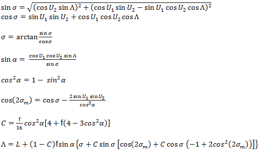
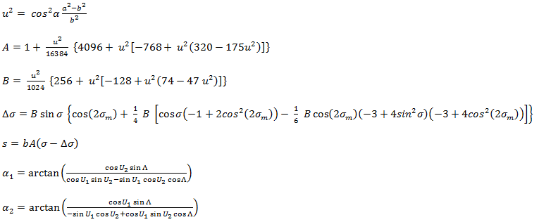
When Λ has converged to the desired degree of accuracy (10-12 corresponds to ~ 0.06mm), evaluate the following:
Antipodal points
The Vincenty Inverse method fails to converge for points that are nearly antipodal. In this case, the distance is then calculated as a great circle on a spherical Earth.
D = 1852 * 60 * cos-1(((cos(A + B) + cos(A - B))*cos(L) - cos(A+B) + cos(A - B))/2.0)
Where:
| All trigonometry is in degrees (not radians) | |
| 1852 | = the number of metric meters in a nautical mile |
| 60 | = the number of seconds in a degree of arc |
| L | = the difference in longitude between points P and Q, |
| A | = latitude of point P, |
| B | = latitude at point Q. |
Note: When the great circle distance calculation is used, a message is sent the Message dialog box.
See also
About 3D projections
Mapping page of the EV File Properties dialog box
What is affected by transducer geometry
About echograms
About cruise-tracks
About scenes
3D single targets graph
Exporting scenes
About degrees and minutes