Beam compensation
|
Beam compensation is applied to a TS value to correct it for transducer directivity, that is to correct for the location of the target within the transducer beam pattern. A beam pattern represents the relative sensitivity of the transducer as a function of spatial angle. See also: Beam pattern graph example. Beam compensation modelsBeam patterns can be modeled and the models may be used to estimate what the TS value would be if the target was central in the beam. Many models cite limits of validity. |
Below: Two dimensional beam pattern shows the variation of the signal strength of the main lobe and side lobes. 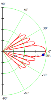 |
Beam compensation methods
The following methods are available for determining beam compensation.
Simrad split-beam method
Ex60 data, EK80 single frequency data
The Simrad split beam method works by determining the angular position of a target within the beam, and calculating the beam compensation from that position. The beam compensation is calculated from a second order polynomial fit to an ideal function. The Simrad beam compensation is two-way beam compensation. See Simrad LOBE used by Ex60 data and the Single target detection operator.
EK80 pulse compressed data
The Simrad split beam method works by determining the angular position of a target within the beam, and calculating the beam compensation from that position. The beam compensation is calculated from a second order polynomial fit to an ideal function. Echoview reads frequency dependent information from the data file and evaluates values for calibration settings and beam compensation as required. The Simrad beam compensation is two-way beam compensation. See Simrad LOBE used by EK80 pulse compressed data and the Single target detection - wideband operator.
BioSonics split-beam method
The BioSonics split beam method works by determining the angular position of a target within the beam, and calculating the beam compensation from that position. See BioSonics split-beam compensation for details.
HTI split-beam method
The HTI split beam method works by determining the angular position of a target within the beam, and calculating the beam compensation from that position. The beam compensation is calculated from a fourth order polynomial that models the transducer's beam pattern. See HTI split-beam beam compensation for more information.
BioSonics dual-beam method
The dual beam method works by determining the difference in target strength between two beams, one wide the other narrow. The difference in target strengths is attributed to a difference in the beam compensation (as the actual target strength of the target is independent of beam width). Echoview applies the narrow-beam beam compensation. See Dual-beam beam compensation and Dual beam (method 1) or Dual beam (method 2) for more information.
Furuno split-beam method
The Furuno split-beam method works by determining the angular position of a target within the beam, and calculating the beam compensation from that position. The beam compensation is a proprietary Furuno algorithm. For more information about the Furuno beam compensation model please contact Furuno.
Sonic split-beam method
The Sonic split-beam method works by determining the angular position of a target within the beam, and calculating the beam compensation from that position. The beam compensation is calculated using the J1 solution to the Bessel function. See Sonic split-beam beam compensation.
See also
Single target detection algorithms
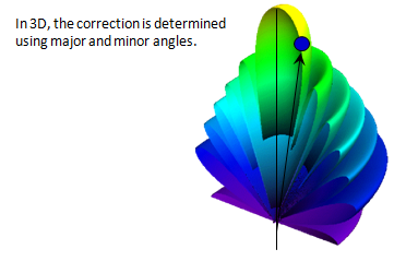
Major-axis beam compensation graph
Minor-axis beam compensation graph
Off-axis beam compensation graph