Wideband ringing, side lobe echo from a trawl body
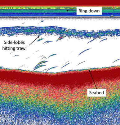
Figure 1. Excerpt from Kloser and Sutton (2020) Figure 6: Example broadband echogram (35-45 kHz) showing transdcuer ringdown and the side-lobe effect.
Kloser and Sutton (2020) investigated the use of broadband echosounders and wide beam transducers. They found that wide beam transducers where useful but they encountered these limitations:
- "Sidelobes hit trawl (Figure 6),
- Greater acoustic dead zone,
- Greater transducer ring-down (Figure 6),
- Multiple targets in sampled volume (horizontal separation)."
Side lobe and beam pattern
The echogram of Figure 1, shows half-moon shaped fish echoes detected by the main lobe of the transducer. The identified side lobe trawl body echoes are notably similar in value to the fish echoes, which is unexpected because the first transducer side lobe is significantly less sensitive than the main lobe and lies well outside of the 3dB beam angles of the main lobe.
To demonstrate the relative sensitivity of side lobe to main lobe, the 1.2.2.3 directivity example used by Demer et al (2015)) displays a first side lobe sensitivity of about 10% compared to the main lobe (Figure 2), which has a 3dB beam angle of approximately 13 degrees (Figure 3).
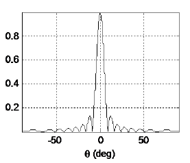
Figure 2. Excerpt from Demer et al (2015) Figure 1.3 Equivalent representation of transducer directivity pattern b(θ) (dimensionless) versus angle (θ) off the beam axis (θ = α, or β) of a piston transducer with a diameter equal to 50 wavelengths. α is the minor-axis angle and β is the major-axis angle.
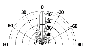
Figure 3. Excerpt from Demer et al (2015) Figure 1.3 Equivalent representation of transducer directivity pattern B(θ) = 10 log10 b(θ) (dB re 1) versus angle (θ) of a piston transducer with a diameter equal to 50 wavelengths.