New in Echoview 2.00
The change from Echoview 1.51 to Echoview 2.00 was dramatic and involved some significant migration considerations for existing users. These were documented external of the help file in a paper titled Echoview Conversion Guide: For users migrating from Echoview 1.51 to Echoview 2.00 and higher (September 2000). Reproduced here are the sections from that document describing new features in Echoview 2.00.
- New Concepts
- Where to find
- Filesets
- Variables
- Echograms
- Lines
- Single targets
- Processing
- Virtual variables
- Additional applications
New Concepts
Some new terms and concepts have been introduced in Echoview 2, which should be understood before working with the application.
Filesets
Filesets are the means by which data files are grouped in Echoview 2. The Filesets window replaces the File List window in version 1.51. There can now be more than one fileset per EV file. Consult Chapter 3 for further information regarding filesets.
Variables
An Echoview "variable" is a generalized concept referring to data that can be displayed as an echogram. In practice this means time-tagged data collected over the water column that can be displayed in two dimensions: time in the horizontal dimension and depth in the vertical dimension.
A raw variable is a variable derived directly from data stored in a data file. Which raw variables are available from a particular set of data files is dictated by the data file type, the number of transducers on the echosounder, the settings on the echosounder and logging software, and the ability of Echoview to interpret the data.
Echoview 1.51 supported the display of a single raw variable per EV file. In some cases it was possible to swap between two variables; for example, you could choose either the narrow or wide beam when using Kaijo or BioSonics dual-beam sounders. For other applications it was necessary to create an EV file for each raw variable, as was the case if you wished to view data from multiple transducers in Simrad EK500 or Kaijo data files.
Echoview 1.51 provided only limited facilities for analyzing data stored in multiple EV files. In Echoview 2, a single EV file can contain all the raw variables relating to a given survey or transect, and the data can be viewed independently or simultaneously as required.
Echoview 2 can also read and display a wider range of raw variables from data files than Echoview 1.51. This has been made possible by the ability in Echoview 2 to support high-resolution data and display single target detections from Simrad data files.
Virtual variables are user-defined and permit composite echograms and analysis based on the synthesis of one or more variables, using a range of inbuilt algorithms. Virtual variables add a new level of flexibility in echosounder data analysis, and are particularly valuable for multi-frequency analysis.
The algorithms used to create virtual variables are called operators in Echoview 2, and the input variables to an operator are referred to as operands. Operands may be raw variables, other virtual variables, or a combination of the two. Consult Chapter 9 for further information on virtual variables.
The Virtual Echogram module is required to make full use of virtual variables in Echoview 2. To purchase this module contact SonarData. The contact details are on page 2.
Where to find
Options and properties
In Echoview 1.51, most of the properties relating to data files, echograms and operating parameters were set using the View Options dialog box, invoked through the toolbar or the View menu.
Echoview 2 separates these properties into three logical groups: those relating to EV files, those relating to filesets and those relating to variables. Consult Chapters 3 and 4 for a discussion of the properties relating to filesets and variables respectively.
EV file properties
The EV File Properties dialog box contains seven pages, which appeared in the Echoview 1.51 View Options dialog box:
- The Export, Schools, Cruise Track and Echogram pages appear as they did in Echoview 1.51
- User Ping Status is now called User Status
- File List is now called EV file page
- Bottom Detection page is now Line Pick page
There are also two additional pages: Lines and Notes.
The settings that were on the Constants page are now maintained on a per-variable basis and may be found on the Calibration page of the Variable Properties dialog box.
Similarly, many of the settings from the Echogram, Single Targets and Integration pages are now found on the Data, Display and Processing pages of the Variable Properties dialog box.
Consult Chapter 4 for a discussion of variables and the Variable Properties dialog box.
To open the EV File Properties dialog box:
- Click the EV File Properties button
 on the toolbar; or
 - Choose EV File Properties from the View menu; or
- Press F6 on the keyboard.
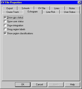
The EV File Properties dialog box showing the Echogram page.
The Data menu
The Echoview 1.51 Data menu has been replaced with a context-sensitive menu, which changes according to the active window.
Adding and removing data files is now performed in the Filesets window discussed in Chapter 3.
Do not confuse the Data page of the Variable properties dialog box with the Echoview 1.51 data menu.
File List
The File List window has been replaced by the Filesets window, discussed in Chapter 3.
Toolbar functions
Some toolbar buttons have been added in Echoview 2, others have changed or have been removed.
The buttons below are available when an echogram is the active window.
![]()
Echoview 2 toolbar.
Echoview 2 toolbar functions
|
Icon |
Name |
Description |
|
|
EV file Properties |
Opens the EV File Properties dialog box |
|
|
Variable Manager |
Opens the Variable Manager dialog box |
|
|
Color Legend |
Now opens the Color Legend dialog box. This button toggled between color schemes in Echoview 1.51. |
|
|
Region Properties |
Opens the Region Properties dialog box. This command was available through the right-click context menu in Echoview 1.51. |
|
|
Variable Properties |
Opens the Variable Properties dialog box. |
Print and Print preview
The Echoview 1.51 Print and Print Preview toolbar buttons have been removed in Echoview 2. They remain available through the File menu.
Zoom
The Echoview 1.51 Zoom toolbar buttons have been removed. Zooming is now achieved through the:
- Right-click context menu
- View menu; or
- Shortcut keys. Refer to the section on Keyboard shortcuts below for a complete list of changes to keys.
Keyboard shortcuts
The table below shows keyboard the shortcuts which have been added, removed or now perform a different function in Echoview 2.
|
Function |
Echoview 1.51 |
Echoview 2 |
|
Zoom in |
s or z or Ctrl+z |
s |
|
Zoom out |
w or o or Ctrl+o |
w |
|
Unzoom |
Ctrl+u |
u |
|
Move up 1 page (when zoomed in) |
- |
Page Up |
|
Go to top of echogram (when zoomed in) |
- |
Ctrl+Page Up |
|
Move down 1 page (when zoomed in) |
- |
Page Down |
|
Go to bottom of echogram (when zoomed in) |
- |
Ctrl+Page Down |
|
Scroll to left-hand edge of echogram |
- |
Home |
|
Scroll to right-hand edge of echogram |
- |
End |
|
Synchronize all echograms |
- |
A |
|
Decrements the minimum SV setting and updates the display |
F11 or - |
Now decrements the color minimum |
|
Increments the minimum SV setting and updates the display |
F12 or + |
Now increments the color minimum |
|
Decrements the maximum SV setting |
Shift+F11 |
Now decrements the color range |
|
Increments the maximum SV setting |
Shift+F12 |
Now increments the color range |
|
Decrements the noise power setting |
Ctrl+F11 |
Now decrements the time-varied threshold applied to the data |
|
Increments the noise power setting |
Ctrl+F12 |
Now increments the time-varied threshold applied to the data |
Filesets
Echoview 2 uses filesets to manage groups of data files. A single EV file can contain multiple filesets, each of which can contain multiple data files. In Echoview 1.51, an EV file can contain only one group of data files and display and analyze the data from one transducer.
If your data are in a single group of data files, you’ll find Echoview 2 is functionally similar to Echoview 1.51, in that you’ll be working with a single fileset. However, the data file handling capabilities of Echoview 2 have been extended to allow:
- A single EV file to provide access to data from multiple transducers.
- Multiple variables to be analyzed from each transducer within a fileset.
- An EV file to contain multiple filesets.
Multiple filesets will be useful if you work with:
- Echosounders or echologging software, such as the Simrad BI500, that logs data from multiple transducers into separate data files.
- Data logged from multiple echosounders at the same time.
- Global Position System (GPS) data that are logged in a separate file to your echosounder data. In this case the GPS data must be loaded into the primary fileset and the echosounder data into a secondary fileset.
The Filesets window
The Filesets window is similar to the File List view in Echoview 1.51 except that:
- There is now a second section listing the raw variables present in the data files for each fileset.
- There can be more than one group of data files present as Echoview 2 supports multiple filesets. Tabs in the upper section of the window indicate additional fileset pages.
The Filesets window showing the upper and lower sections and tabs from multiple filesets.
Adding and removing data files
The procedure for adding and removing data files remains the same as it was in Echoview 1.51, except the dialogs are now invoked through the Add and Remove buttons which appear on the right-hand side of the Filesets window.
To add data files to a fileset:
- Click the Add button, which appears on the right-hand side of the Fileset window.
- Select one or more files. Multiple files may be selected using the Ctrl key (single files) or Shift key (range of files).
- Click Open to add the selected files to the EV file.
To remove data files from a fileset:
- Select the data file to be removed, in the Data files section of the Fileset window.
- Click the Remove button, which appears on the right-hand side of the Fileset window
To select multiple files when adding or removing data files:
- Use the SHIFT key to select a range of files.
- Use the CTRL key to select individual files.
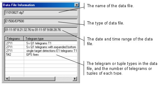
Data file information
Echoview 2 contains a Data File Information dialog box that displays information relating to the data file.
To invoke the Data File Information dialog box:
- Select a data file in the Data files section of the Fileset window.
- Click the Information button that appears on the right-hand side of the Fileset window.
The Data File Information dialog box will appear as shown below.
The Data File Information dialog box.
Fileset properties
The Fileset Properties dialog box is automatically presented when a new fileset is created. It can also be invoked at any other time.
Use the Fileset Properties dialog box to name the fileset and to enter a time offset if required. The time offset may be used if two sets of data have been recorded from devices whose time base differs.
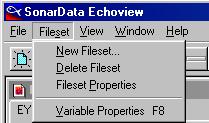
To invoke the Fileset Properties dialog box, choose Fileset Properties from the Fileset menu.
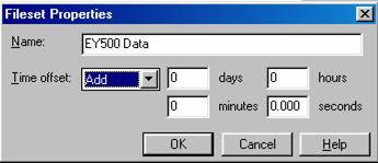
The Fileset Properties dialog box.
The Fileset menu
The Fileset menu appears when a Filesets window has the focus. It appears where the Data menu was located in Echoview 1.51.
The Fileset menu.
Creating new filesets
To create a new fileset:
- Choose New Fileset from the Fileset menu. The Fileset Properties dialog box opens and a new fileset is created.
- Enter the Name of the new fileset or accept the default.
- Enter the Time Offset details or accept the default.
Multiple file sets are required where:
- Data from one echosounder with multiple variables are stored in different files; for example, BI500 data for two or more frequencies; or
- Two or more echosounders are operated at the one time; for example, Simrad EY500 and BioSonics DT4000 echosounders operated simultaneously.
Note:
Any GPS or vessel log data in filesets other than the primary fileset are ignored by Echoview.
Deleting filesets
To delete a fileset:
- Ensure the fileset you want to delete is the active page of the active window; that is, its name tab is foremost and its elements visible.
- Choose Delete Fileset from the Fileset menu.
Note: The primary fileset cannot be deleted.
Variables
Variable properties
![]()
Variable Properties dialog box showing eight pages. Pages will change according to the context.
The Variable Properties dialog box has a range of settings to control the way the selected variable is used and displayed.
To open the Variable Properties dialog box:
- Click the Variable Properties icon
 on the toolbar; or
 - Press F8 on your keyboard; or
- Click the Properties button on the Filesets window; or
- Choose Variable Properties from the Echogram, Filesets or Graph menu.
Note:
- If the Filesets window is active, choose the desired variable from the Raw Variables section prior to invoking the Variable Properties dialog box.
- The Variable Properties dialog box can also be invoked for a virtual variable using the Variable Manager dialog box. Consult Chapter 9 for further information on virtual variables.
- The Variable Properties dialog box is variable-specific in that it displays pages relevant to the selected variable; for example, the Calibration page is only displayed if a raw variable is selected.
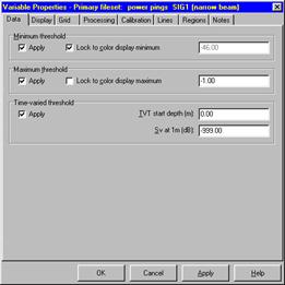
Thresholds (maximum and minimum SV)
Echoview 2 offers increased flexibility in setting thresholds and changing the way in which your data are displayed. Threshold settings are no longer restricted to integer values, and display settings have now been separated from the settings used in integration.
Echoview 1.51 allowed you to specify a Minimum SV on the Echogram page of the View Options dialog. This was used to set:
- The value which corresponded to the first color in the color scheme when displaying echograms, and
- The value used as a minimum threshold when performing integrations.
Note: Thresholding only occurred if Apply Minimum SV threshold was checked on the Integration page of the View Options dialog.
Echoview 2 allows these two values to be set independently. The Color minimum is set on the Display page of the Variable Properties dialog, and the Minimum threshold is set on the Data page of that dialog. The Data page also allows you to simulate the Echoview 1.51 behavior by checking Lock to color minimum on the Data page.
Echoview 1.51 also allowed you to specify a Maximum SV on the Echogram page of the View Options dialog. This value was used as:
- A maximum threshold when displaying echograms; and
- A maximum threshold when performing integrations if the Apply Maximum SV threshold was checked on the integration page of the View options dialog box.
Note: In Echoview 1.51 the maximum threshold was not the same as the upper limit of the color scheme; that is, the largest value that was displayed using a color. The upper limit of the color scheme was always a fixed increment above the Minimum SV. That increment was fixed by the color scheme (71 dB for the default color scheme).
Echoview 2 allows direct control of the color range which can now be set separately from the maximum threshold. The Color range is set on the Display page of the Variable Properties dialog, and the Maximum threshold is set on the Data page of that dialog.
The Data page also allows you to lock the maximum threshold to the color maximum; that is, the color minimum plus the color range. This is done by checking Lock to color maximum on the Data page.
Background noise and time varied thresholds
Background noise is handled differently in Version 2 compared to version 1. If you used background noise export variables such as SA_noise or SV_noise in version 1, then we recommend close attention to the changes.
Echoview 1.51 had only a single background noise setting: Noise power (dB re 1 Watt at 1m) which was set on the Echogram page of the View Options dialog. This was used to:
· Apply a Time Varied Threshold to the display (this was NOT applied to the data).
· Calculate mean noise SV and mean noise SA when performing integrations.
In Echoview 2 the noise level to define the time varied threshold and the noise level to calculate background noise export variables are independent.
A time-varied threshold (TVT) may be applied on the Data page of the Variable Properties dialog. Note that the keyboard shortcuts, Ctrl+F11 and Ctrl+F12, will affect this value when used in an echogram window. The time-varied threshold is applied to the data and not just to the display and will always affect integration results.
The background noise used for calculating mean noise SV and mean noise SA (now called SV _noise and NASC_noise) are set on the Processing page of the Variable Properties dialog.
In Echoview 2 the background noise level is specified in terms of SV at 1m (dB) on SV echograms and TS at 1m (dB) on TS echograms. The units are different from the noise power setting in Echoview 1.51 although any value in a version 1.51 EV file will be correctly converted if the file is opened in Echoview 2.
The new units incorporate the calibration settings of the echosounder.
![]()
![]()
![]()
Where P = received power, Ec = calibration constant, a = absorption coefficient and r = range from transducer face
Echoview 2 also supports background noise subtraction using the virtual echogram module. This can be implemented using the Data Generator operator to create a noise echogram and the Linear Minus operator to subtract the noise echogram from the original echogram. Using the virtual echogram module for this task enables the user to see the results of the noise correction. The user is reminded that noise correction by subtraction relies on ensemble averaging to subtract a mean noise from the mean level of (noise plus signal). Virtual echogram resample operators can be used to re-sample or average the data in cells prior to noise correction.
Note:
If a draft is applied in Echoview or a draft correction was applied by the echosounder during data logging, then the time-varied gain or time-varied threshold start depth must be adjusted so that the depth of a sample value minus the TVT start depth is equal to the range from the transducer face to the sample value. Caution is advised with Simrad EK500 data files where the effective draft applied to the data by the EK500 may not be exactly equal to the draft entered into the EK500. Refer to Draft Correction Warning page in the Echoview help file.
Data page of Variable properties dialog box
This page is used to set all thresholds that are applied to the data. Note that a start depth can be specified for the TVT.
The Data page of the Variable Properties dialog box.
Processing page of Variable properties dialog box
Elements of the version 1.51 Single Targets and Integration pages are now found on this page. Exclusions and Background noise are set on the Processing page as shown below.
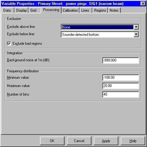
The Processing page of the Variable Properties dialog box.
The Frequency distribution settings are used to control the bin size used to determine and graph a frequency distribution of sample values within a selection or region.
Color schemes
Echoview 1.51 supported toggling between two fixed echogram color schemes, each with a limited number of colors. Echoview 2 allows you to choose between a number of pre-defined echogram color schemes, or lets you create your own.
User-defined color schemes can be created and edited with the Echocolor program supplied with Echoview. User-defined color schemes are stored as .EVC files in the Color Schemes folder that is located in the folder in which Echoview was installed.
Note: If you add, remove or change the color-scheme files in this folder you will need to restart Echoview before those changes take effect.
Each user-defined color scheme can have up to 1024 distinct colors. The colors used for drawing regions, lines and grids may also be specified in the color scheme.
The color scheme for each variable can be changed in the Display page of the Variable Properties dialog box. To support this increased flexibility, Echoview 2 requires the display settings on your computer to be set to at least 16-bit color (65536 colors). Better display results will be obtained with 24 or 32-bit color.
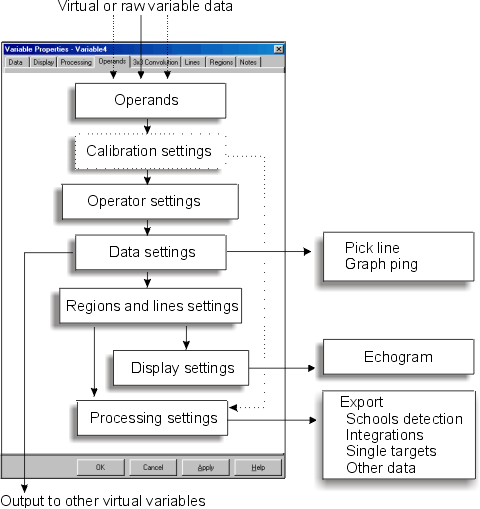
Understanding variable property settings
The pages that appear in the Variable Properties dialog box operate sequentially to affect output to the echogram or data export. This is explained in the Raw variable properties diagram below and the Virtual variable properties diagram on page 42.
The properties of each variable must be set independently.
Raw variable properties
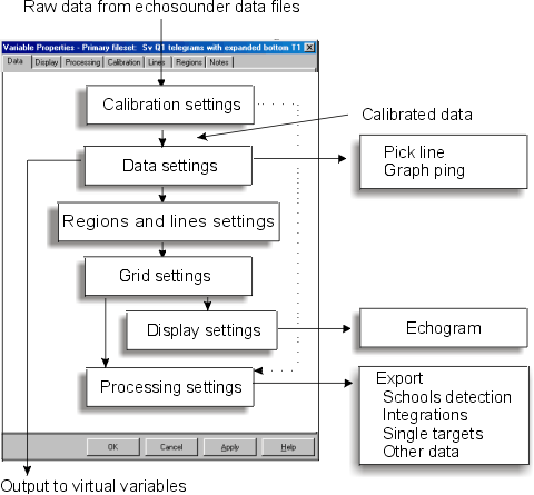
Flow diagram showing effect of variable properties settings on raw variables.
The application of the settings, in the Variable properties dialog box to your data, can be illustrated using a fluid flow analogy. The data flows from the data file into Echoview and is changed by each of the boxes in the figure above. The data can take several directions to arrive at the outputs on the right hand side of the figure. You can work back from a particular output to see which Echoview settings have affected the data.
Some examples:
- Data that flows out of a variable as an output to virtual variables will have passed through and been modified by calibration settings and Data settings, but it will not have been affected by the grid settings or the processing settings.
- Export variables calculated by integration will have passed through and been modified by calibration, data, grid, regions and lines, and processing settings.
Where an EV file has a number of variables it is important to remember that all variable properties must be set independently for each variable.
Echograms
Echoview 2 now supports multiple echograms. An echogram may be viewed by:
- Choosing the desired variable from the View menu; or
- Selecting a variable in the Filesets window; or
- Selecting a variable in the Variable Manager dialog box.
Consult Chapter 9 for further information on the Variable manager dialog box.
If a filesets window is active:
- Select the desired variable from the Raw variables section of the Filesets window.
- Click View.
Synchronizing echograms
When more than one echogram window is open the echogram displays can be aligned by using Synchronize echogram. Each echogram will be adjusted to fit the same time and depth ranges within each window. The echogram with the focus when the synchronize command is used (from the right-click context menu or the keyboard short cut A) will control the time and depth range used for all windows. Windows that are minimized will not be synchronized.
The View menu
The View menu showing the variables of multiple filesets..
The Echoview 2 View menu differs from Echoview 1.51 in that:
- An echogram is selected for a particular variable in the EV file.
- It is context-sensitive; that is, there are five extra commands when an echogram is the active window.
Menu commands
Echogram
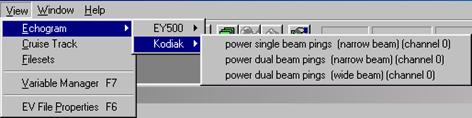
To view an echogram:
- Choose Echogram from the View menu; then
- Select a fileset from the Fileset cascading menu; then
- Select a variable from the variable cascading menu.
Cruise Track
The Cruise Track command and the Cruise Track window has not changed since Echoview 1.51.
Filesets
To view the Filesets window, choose Filesets from the View menu. Filesets are explained in Chapter 3.
Variable Manager
To view the Variable Manager dialog box, choose Variable Manager from the View menu. The Variable manager is explained in Chapter 9.
EV file Properties
To view the EV File Properties dialog box, choose EV file Properties from the View menu. EV file properties are explained in Chapter 2.
Commands available when an Echogram window is active
The View menu has five extra commands when an echogram has the focus:
Color Legend
The Color Legend dialog box is now modeless. This means that the dialog box may remain on the screen as you perform other tasks. If you change echogram windows, the Color legend will change to match which ever echogram window has the focus.
Zoom In, Zoom Out, Unzoom
These commands have not changed since Echoview 1.51 except that the shortcut key z is no longer available. Use s instead of z to zoom in.
Region Properties
To open the Region Properties dialog box, choose Region Properties from the View menu. This command is no longer available from the right-click context menu.
The region properties dialog has not changed.
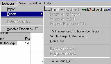
The Echogram menu

Echogram menu showing export options.
The Echogram menu appears where the Data menu was located in Echoview 1.51, when an echogram window is active.
Import, Detect Schools
These commands are identical to those available from the Data menu in Echoview 1.51.
Export
The Export command remains functionally identical to Echoview 1.51.
The To Generic HAC option, visible on the menu above, will be available in future releases of Echoview. This will allow you to export data in the HAC format.
Note: This will remain a draft format until the FAST HAC tuple co-ordination committee approves the tuples.
Variable Properties
To open the Variable Properties dialog box, choose Variable Properties from the Echogram menu.
Consult Chapter 4 for further information on the Variable Properties dialog box.
The Graph menu
![]()
The Graph menu.
The Graph menu appears where the Data menu was located in Echoview 1.51 when a graph ping window is active.
The menu can be used to invoke the Variable Properties dialog box.
Lines
Echoview 1.51 supported the display of only one line (the bottom) but had four other hidden lines that you could use:
- Surface exclusion at a fixed depth not visible on the echogram (optional).
- Sounder-detected bottom sourced from the data file and used as the initial position of the bottom line (not editable or visible).
- A visible and editable bottom line.
- A bottom exclusion line at a fixed offset from the bottom. This was not visible and its use was optional.
Echoview 2 extends the use of lines to allow much greater flexibility. In Echoview 2, you can:
- Have any number of lines.
- Specify and assign names to lines as required.
- Choose which lines are visible on a specific echogram. This is performed through the Lines page of the Variable Properties dialog box.
- Nominate which line should indicate surface exclusion (the exclude-above line). This is performed through the Processing page of the Variable Properties dialog box.
- Nominate a line to indicate bottom exclusion (the exclude-below line). This is performed through the Process page of the Variable Properties dialog box.
- Edit individual lines through the echogram window.
Note: A line must be made active to be editable. The active line can be selected on the Lines page of the Variable Properties dialog box. - Create, delete and rename lines through the Lines page of the EV File Properties dialog box.
If a variable has a sounder-detected bottom, Echoview 2 also allows you to display this bottom line on the echogram.
The colors in which lines are displayed may be changed by editing the color scheme.
Active lines
When an EV file is created, it does not contain an active line. A line must be created and made active before it can be drawn, picked or edited. One line only can be active at any time.
Lines in converted EV files
When opening Echoview 1.51 files within Echoview 2, up to four lines will be visible whereas only one was visible in Echoview 1.51. This may make the display more complex, however any of the lines may be hidden for specific variables, using the Lines page of the Variable Properties dialog box. See Lines for "exclude-above" and "exclude-below" under Processing on page 33.
Importing lines
Echoview will now offer you the choice of creating a new line or extending/overwriting an existing line. The existing line will be over-written during common time intervals in the imported and existing lines.
Creating and deleting lines
Lines can be created, renamed or deleted using the EV File Properties dialog box.
To create, rename or delete a line:
- Choose EV File Properties from the View menu.
- Select the Lines page.
To create a new line:
- Click New
- Choose Existing line, Fixed depth or Bottom pick from current echogram as the source for the new line.
- Choose as the Destination a new line or overwrite an existing line.
The line may also be made active using the Make this line active on current echogram checkbox.
Note: If an active line is not selected when you attempt to draw or pick a line on the echogram, you will be prompted to select or create one.
Single targets
Echoview 2 supports echogram displays of single target detections from Simrad EK60, EK500 and EY500 echosounders. Support for single target data from Kaijo KFC and other sounders is planned for a future update of Echoview 2.
Echoview 1.51 had limited support for Simrad single targets data. The detections in the time and depth range, which corresponded to a selection or region of an echogram, could be plotted on a graph or exported to a CSV file.
Echoview 2 expands this support by treating this data as a separate raw variable type. Single target data can now be viewed directly in its own echogram window. All single target processing and export is now done from an echogram window displaying a single target variable.
Working with single targets
To view a single target echogram:
- Select the single target detection variable in the raw variables section of the filesets window; for example, single target detections E1 Telegrams T1.
- Click the View button to view the echogram.
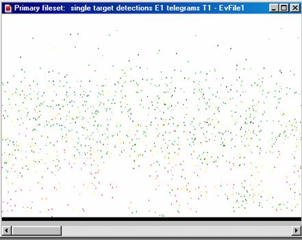
An example of a single target detection echogram
The graphing and export facilities available in version 1.51 are now accessed directly from the single target echogram.
Note: The threshold settings and the surface and bottom exclusion lines will exclude single targets in version 2. These settings were ignored in version 1.51. Calibration settings must be entered in a single target variable, separately from any associated SV variable.
The virtual echogram module provides some advanced functionality for use with single target variables; for example, it is possible to:
- Overlay single target detections on top of a conventional SV echogram. This is useful to visualize the relationship between single detections and schools.
- Calculate a new single target detection variable based on the union, intersection or difference between two single target variables. This is useful for analyzing data collected at multiple frequencies.
Echogram menu
The Echogram menu contains options for single target export, when a single target echogram is active.
Echogram menu showing single target export options.
Processing
Integration
When you integrate a selection, region or cell on the screen, samples included in the integration are now hatched in red. This hatched section now stays visible while zooming or moving around the echogram. The hatching is removed by pressing the Esc key.
When exporting integration by regions, you can now select the classification of the regions you want to export. See the raw variable properties diagram on page 25.
Graphs
Echoview 1.51 had the ability to display the histogram of a plot, of SV value against depth, for all data points in a ping. Echoview 2 extends this feature, allowing the plot of all data points in the multiple pings of a vertical selection.
The new graph, Frequency distribution, can be plotted for any region or selection on most variable types. The graph is a histogram of the frequency distribution of samples within the region or selection. The histogram bin range and number of bins are controlled on the processing page of the Variable Properties dialog box.
In Echoview 1.51 the Frequency distribution graph was available only for single target TS data.
Lines for exclude-above and exclude-below
Echoview 1.51 had the ability to exclude data below the bottom (plus an offset) and to exclude data above a constant surface exclusion depth.
Echoview has extended this facility by allowing the user to select any line to exclude data above and any line to exclude data below. These commands are in the Properties page. In general the Exclude below line is the bottom or a line that is offset from the bottom.
The Bottom Detection page of the View Options dialog in version1.51 is now the Line Pick page in the EV file dialog.
Regions
Echoview has enhanced the flexibility of working with regions, for example:
- Bad data regions can now be assigned classifications.
- Regions of particular classifications can be set to "not visible" in any variable. Regions that are set "not visible" ARE NOT available for display or processing. Thus if bad data regions of some classifications are not visible, then the bad data areas will not be excluded from integration.
Changes to the on-screen integration results dialog
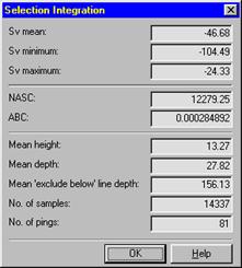
New selection Integration dialog
NASC = Nautical area scattering coefficient = sA in version 1
ABC = Area backscattering coefficient
NASC = ![]() ABC
ABC
This cell integration dialog box, region integration dialog box and selection integration dialog box all contain the same information.
Changes to export variables
The names of a number of export variables have been changed in Echoview 2. The changes follow recommendations being discussed at the ICES FAST meetings. ICES FAST had not made a final recommendation at the time changes were made to Echoview 2. However, following the argument presented to the FAST meeting, that there was potential for confusion in the use of some names, we have changed variable names in the applications.
Other names have changed because of changes in Echoview (e.g. bottom depth is now exclude-below line depth.
Bathymetric data export files
|
Old name |
New name |
Notes |
|
Bottom depth |
Line depth |
Echoview 2 uses lines not bottoms. |
|
Bottom status |
Line status |
Echoview 2 uses lines not bottoms. Status values and meanings remain the same. |
Frequency Distribution export files (for single target data)
There are substantial changes to the format of these files.
|
Old name |
New name |
Notes |
|
Region ID |
No longer exported. |
|
|
Region name |
Region Label |
Change of name for internal consistency. |
|
Region Classification |
The region classification was not output in Echoview 1.51. |
|
|
Targets_failed_thresholds |
The number of single targets that are less than the minimum threshold or greater than the maximum threshold set on the Data page of the variable properties dialog box. |
|
|
Targets_Failed_Filter |
Targets_Failed_Filter |
A count of the number of targets that did not pass the angle or TS-compensation filters on the Data page of the variable properties dialog box. |
|
Targets_Excluded |
Count of number of targets that did not pass the exclude above/below line settings on the processing page of the variable properties dialog box. |
|
|
Targets_Missed_Bins |
Targets_Missed_Bins |
Count of the number of single targets with TS less than the minimum TS or greater than the maximum TS values for the frequency distribution. |
Integration export files
Cell related export variables
|
Old name |
New name |
Notes |
|
Interval |
Interval |
Change to numbering for GPS distance grids. In version 1.51 the first interval was always interval 1 and started with the first ping in the EV file. In Echoview 2 the first GPS fix is the zero distance reference and interval 1 will start at the first GPS fix. Interval number zero (or lower numbers) may precede interval 0. |
|
sA_mean |
NASC |
Name change only. |
|
SA_noise |
NASC_noise |
Name change only. |
|
PRCSa |
PRC_NASC |
Name change only. |
|
ABC |
Area Backscattering Coefficient. |
|
|
ABC_noise |
Area backscattering Coefficient due to background noise. |
|
|
PRC_ABC |
Weighted ABC calculated in the same way as NASC. |
Interval related export variables
|
Old name |
New name |
Notes |
|
Depth_int |
Exclude_below_depth |
Mean depth of exclude-below line over pings in interval or region. Only pings with a good line status for the exclude-below line will be included in the average. A value of 999.99 indicates no good line picks (or no line picks) over the interval. |
Processing related export variables
|
Old name |
New name |
Notes |
|
Gain_const |
Gain_const |
Echosounder constant. In Echoview 2 this is calculated only for EchoListener data and is otherwise set to 999.9. |
|
Noise_power |
Noise_ SV_1m |
Now the SV due to background noise at 1 m range from transducer. |
|
Surface_exclusion |
Exclude_above_line_applied |
1 = exclude-above line applied |
|
Surface_exclusion_depth |
Mean_exclude_above_line_depth |
-999.99 in all cases. Calculation not yet implemented in Echoview 2. |
|
Below_bottom_excluded |
Exclude_below_line_applied |
1 = Exclude-below line applied |
|
Bottom_offset |
Bottom_offset |
0 (always) |
Region related export variables
|
Old name |
New name |
Notes |
|
Region ID |
Internal Echoview region ID number. |
Schools related variables
|
Old name |
New name |
Notes |
|
Corrected_image_are |
Corrected_area |
Name change only. |
|
Corrected_amplitude |
Corrected_mean_amplitude |
Name change only. |
|
Vertical_roughness |
Vertical_roughness |
The implementation of this variable is under review. We do not recommend using this variable until future notice. |
|
Horizontal_roughness |
Horizontal_roughness |
The implementation of this variable is under review. We do not recommend using this variable until future notice. |
SV value export files
The value for each sample in a region can be exported to a CSV file for export. Values are exported for the bounding rectangle of non-rectangular regions. The value exported for samples within the bounding rectangle and outside the region has been changed from 99999.9 to +9.9e37.
Virtual variables
Echoview 2 introduces "virtual variables". A virtual variable is the result of applying an algorithm or "operator" to one or more input variables or "operands". Operands may be raw variables, other virtual variables or a combination of the two.
An echogram of a virtual variable is called a "virtual echogram".
Data types
The data for every variable in Echoview 2 is of a particular "data type". The following data types are supported:
- SV - volume backscattering strength calculated using 20 Log R in dB units.
- TS - target strength calculated using 40 Log R in dB units.
- Unspecified dB - dB values that are neither SV nor TS.
- Linear - normal numbers with unspecified units.
- Single target detections - detected targets with a depth, angular position and target strength as a TS value.
- Color - values stored as 24-bit RGB quantities, with separate red, green and blue intensities in the range 0 to 255.
- Boolean - every value is either 0 (false) or 1 (true).
The data type of a variable is displayed in the Notes page of the Variable Properties dialog box.
The raw variables supported by Echoview are either SV or single target detection data types. Raw TS variables will be supported in a future release of Echoview 2.
Virtual variables can be of any supported data types - the data type being determined by the operator and the data types of its operands, for example:
- The Blur operator accepts a single operand of dB, Linear or Color types. A virtual variable using the Blur operator has the same type as its operand.
- The SV to TS operator accepts a single SV variable. Its output is of the TS data type.
The behavior of each operator is listed in the table below.
Using virtual variables
Operators can be chained by creating additional virtual variables; that is, by using the output of one virtual variable as input to another. The operators implemented in Echoview 2 have been chosen for their generality to allow maximum flexibility in visualizing and analyzing data.
Virtual variables can be created and virtual echograms viewed without purchasing the Virtual Echogram module. This module is required in order to perform any of the following operations on a virtual echogram:
- Line drawing and picking
- Region creation and editing
- Integration
- Export
- School detection
Variable Manager
The Variable Manager has been introduced to provide a central location to:
- Create new virtual variables
- Delete virtual variables
- Copy virtual variables
- View the properties of variables
- View echograms
To open the Variable Manager dialog box:
- Click the Variable Manager icon
 on the toolbar; or
 - Choose Variable Manager from the View menu; or
- Press F7 on your keyboard.
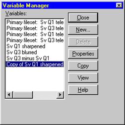
The Variable Manager dialog box.
Commands available from the Variable Manager are described below.
New
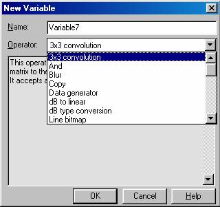
New Variable dialog box.
The New Variable dialog box is used to create virtual variables based on existing variables. To create a new virtual variable:
1. Click the New button on the Variable Manager dialog box.
2. Type a name in the Name box or accept the default.
3. Choose an operator from the drop-down list. The operators are described in the table below.
The Variable Properties dialog box will appear with the Operands page selected to allow you to select the operands for this operator.
Delete
Click Delete to delete the selected variable.
Copy
Click Copy to create a copy of a virtual variable. The copy is given the name: Copy of [Variable name].
Note that the copied variable has independent settings to the original variable.
View
Click View to open an echogram of the selected variable.
Properties
Click Properties to open the Variable Properties dialog box for the selected virtual variable.
Note: Virtual variables do not inherit the properties of the variable from which they were created. Virtual variable properties have to be set independently.
Variable Properties dialog box showing the Operand page following the creation of a new virtual variable.
Virtual variable properties
Flow diagram showing effect of variable properties settings on virtual variables
Variable operators
|
Operator |
Description |
|
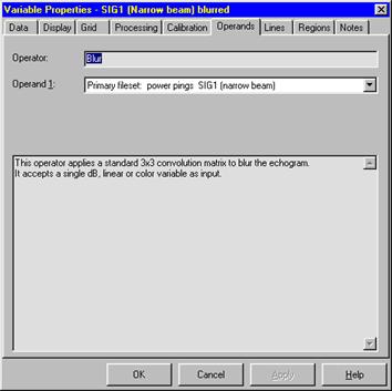
3x3 convolution |
This operator applies a user-specified 3x3 convolution matrix to the echogram. It accepts a single dB, linear or color variable as input. |
|
And |
This operator does a logical AND on two bitmasks. It accepts two Boolean variables as input. |
|
Blur |
This operator applies a standard 3x3 convolution matrix to blur the image. It accepts a single dB or numeric variable as input. |
|
Copy |
This operator does not, by itself change the input variable, however any settings specified on the Data page of the Variable Properties dialog will be applied. The operator is useful when: · You want to display the same variable in two or more windows with different display or processing settings. Use the Copy operator to create a copy variable, then apply display settings to the original and copy variables independently. · Combined with settings on the Data page of the Variable Properties dialog. Use the Copy operator for thresholding purposes. |
|
Data generator |
This operator is used to create data pings. It can create pings with constant SV, TS, other dB and linear values using a specified value. It can also create SV and TS pings with time-varied gain (TVG), based on the SV or TS value at 1 meter and a specified absorption coefficient. It accepts a single variable as input - this variable is used to determine the ping times and geometry. |
|
DB to linear |
This operator applies dB to linear conversion to the individual dB values in the input variable. It accepts a single dB, SV or TS variable as input. The formula used is: linear = 10 ^ (db / 10) |
|
DB type conversion |
This operator is used for changing the type of a variable to a different dB type. This operator does not, by itself, change the input variable, however any settings specified on the Thresholds sheet of the Variable Properties dialog will be applied. It accepts a single dB, SV or TS variable as input. |
|
Line bitmap |
This operator is used to create a bitmap of the area between two specified lines. It accepts a single variable as input - this variable is used to determine the ping times and geometry. |
|
Linear minus |
This operator subtracts two variables in the linear domain. It accepts two dB variables as input. |
|
Linear plus |
This operator adds two variables in the linear domain. It accepts two dB variables as input. |
|
Linear to dB |
This operator applies linear to dB conversion to the individual values in the input variable. Zero or negative input values are converted to "no data" values. It accepts a single numeric variable as input. |
|
Mask |
This operator applies a bitmap mask to another variable. It accepts a dB or numeric variable as its first operand, and a Boolean variable as the second operand. Data corresponding to 1 values in the bitmask are unchanged. Data corresponding to 0 values in the bitmask will be either converted to "no data" values if the "Zero is no data" checkbox is ticked in the Variable Properties dialog. Otherwise, they will be converted to -999.0 (for dB variables) or 0 (for other variables). |
|
Minus |
This operator subtracts two variables. It accepts two dB, numeric or color variables as input. Operand 2 is subtracted from operand 1. |
|
Monochrome |
This operator converts a color echogram to monochrome by averaging the red, green and blue color intensities. It accepts a single color variable as input. |
|
Not |
This operator applies a Boolean NOT operation to the individual Boolean values in the input variable. It accepts a single Boolean variable as input. |
|
Or |
This operator does a logical OR on two bitmasks. It accepts two Boolean variables as input. |
|
Overlay |
This operator overlays two echograms to create a color image. The second echogram is laid over the first, so that the first is only visible where there are 'no data' values in the second echogram. It accepts a dB, numeric, Boolean or color variable as the first operand. The second operand must be a dB, numeric or single target variable. |
|
Plus |
This operator adds two variables. It accepts two dB, numeric or color variables as input. |
|
Range |
This operator creates a bit mask (Boolean variable) with a 1 value for each input value that is within a specified range, and a 0 value for each input value that is outside the specified range. "No data" values are always translated to 0. It accepts a single dB or numeric variable as input. |
|
Region bitmap |
This operator is used to create a bitmap of the area corresponding to regions of specified type and/or classification. It accepts a single variable as input - this variable is used to determine the ping times and geometry. |
|
Resample by number of pings |
This operator re-samples the input variable using a fixed number of pings in the time/distance domain, and a specified upper depth, lower depth and number of data points in the depth domain. It accepts a single dB or numeric variable as input. |
|
Resample by time interval |
This operator re-samples the input variable using a fixed time interval in the time/distance domain, and a specified upper depth, lower depth and number of data points in the depth domain. It accepts a single dB or numeric variable as input. |
|
Select |
This operator uses a bitmap to select between values from two other variables. It accepts dB or numeric variables as its first two operands, and a Boolean variable as the third operand. If there is a 1 value in the bitmap then the corresponding data value from the first variable will be used at that position, otherwise the corresponding data value from the second variable will be used. |
|
Sharpen |
This operator applies a standard 3x3 convolution matrix to sharpen the image. It accepts a single dB or numeric variable as input. |
|
ST difference |
This operator returns the single targets in the first variable that are not within a specified distance of any single target in the second variable. It accepts two single target variables as input. |
|
ST intersection |
This operator returns all the single targets in the first variable that are within a specified distance of any target in the second variable. It accepts two single target variables as input. |
|
ST union |
This operator returns all the single targets in the first variable, plus any single targets in the second variable that are not within a specified distance of any target in the first variable. It accepts two single target variables as input. |
|
SV to TS |
This operator applies SV to TS conversion the individual dB values in the input variable. It accepts a single SV variable as input. |
|
To Color |
This operator converts an echogram to a color image. It accepts a single dB, Boolean or numeric variable as input. |
|
TS to SV |
This operator applies TS to SV conversion to the individual dB values in the input variable. It accepts a single TS variable as input. |
Additional applications
Echoview contains three additional applications, which have extensive improvements with the release of Echoview 2. Refer to Echoview help for more information on these applications.
Echolog_EK
Echolog_EK 2 extends the capabilities of version 1.51 and offers a number of improvements. These are summarized below.
Telegram buffering
With Echolog_EK 1.5, occasional loss of telegrams was reported during incidents of extremely high CPU usage by other applications running simultaneously.
Echolog_EK 2 uses a more robust method of buffering telegrams from the EK500.
Settings
Echolog_EK settings can now be modified on-the-fly from within the application. In general, this means it is no longer necessary to manually edit the Echolog_EK2.INI file. Changes in settings will take affect as soon as the OK button is clicked on the Settings dialog box.
To modify settings, choose Settings from the System menu.
Relevant settings from the Echolog_EK.INI created under version 1 will be automatically migrated into a new Echolog_EK2.INI file.
Ports
Echolog_EK 1.5 used three different TCP/IP ports. These were used to:
- Receive data from a Simrad EK60, EK500 or EA500.
- Communicate with Echoview to permit live viewing.
- Communicate with Echoconfig_EK.
All three ports were required to be correctly set for each application. In version 2, only the first setting is required.
Miscellaneous improvements
Additional improvements have been implemented in version 2. Echolog_EK now:
- Displays an estimate of time before disk capacity is reached. This appears in the Network Info dialog box.
- Supports multiple instances of the application on a single computer in order to log data from multiple EK500 sounders. Contact SonarData for further information on this feature.
- Disables Windows power management for the duration of logging. Note that this applies to Windows 98 and Windows 2000 only.
- Permits demonstration usage of up to 45 minutes.
- Has an improved method of calculating This minute logging throughput.
- Includes an Equipment name setting. This defaults to the name of the local computer but may be used to provide a custom name for identifying the EK500. Echoview displays the name during live viewing.
- Allows you to enable or disable the auto-deletion facility. This results in real-time update of application icons, rather than having to restart the application, as was the case in version 1.5. The auto-deletion facility is set using the Settings dialog box.
Echosim_EK
Echosim_EK 2 remains functionally similar to version 1.5 except that:
- Windows power management is now disabled when a file is being sent.
Note: This applies to Windows 98 and Windows 2000 only.
- Some cosmetic improvements have been implemented in the main window.
Echoconfig_EK
Echoconfig_EK 2 now:
- Uses a more robust method of communicating with Echolog_EK and Simrad EK500.
- Supports multiple instances of Echolog_EK on a single computer.
- Allows a simplified setup procedure by no longer requiring TCP/IP port numbers. Only the EK500 IP address, the Echolog_EK IP address and the equipment name need to be specified.
- From version 2.11 Echoconfig allows wildcard reading of EK500 settings.
- The information displayed in the Network Info dialog box has also been improved.