About beam geometry
Echoview supports the identification of target position within a sonar beam, and the definition of beam shape for single beam, split beam and dual beam echosounders is called beam geometry in Echoview. See also About ping modes for a discussion of ping shapes.
Axes
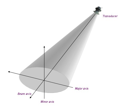
Echoview uses three axes in describing beam geometry: beam axis, minor axis and major axis. Range from the transducer is measured along the beam axis and position in the beam is measured from the beam axis (along the minor and major axes). Minor and major are axis naming conventions, and different manufacturers have adopted different naming conventions for the these two axes. Equivalent axis terminology for leading brands of echosounders are:
|
Manufacturer |
Preferred Minor Axis Terminology |
Preferred Major Axis Terminology |
|
BioSonics |
Minor |
Major |
|
HTI |
Up-down |
Left-right |
|
Simrad |
Alongship or Longitudinal |
Athwartship or Transversal |
|
Precision Acoustic Systems |
y |
x |
Figure 1 below illustrates the axis system.
|
|
|
Figure 1: Beam Axes |
Multibeam
Multibeam echosounders combine many individual beams into one ping, typically depicted as a sector plot. This sector plot depicts a surface, either in the form of a flat sector (for most ping modes) or a conical surface (for ping mode 3). The minor and major axes are defined consistently in Echoview (for each individual beam and all beams together) as follows:
Sector plot
The axes of the individual beams and of the entire sector (viewed as one image) are defined as follows:
Major-axis - in the plane of the sector
Minor-axis - orthogonal to the plane of the sector
Cone
The axes of the individual beams and of the entire sector (viewed as one image) are defined as follows:
Major-axis - tangential to the surface of the cone
Minor-axis - orthogonal to the surface of the cone
Angles
Angles in Echoview are referred to as minor-axis or major-axis angles.
The minor-axis angle is a measure of angle from the beam axis along the minor axis. Looking from the transducer, the positive direction for the minor axis angle is forwards.
The major-axis angle is a measure of angle from the beam axis along the major axis. Looking from the transducer, the positive direction for the major axis angle is to starboard.
Together minor- and major-axis angles and range define a point in the beam.
Directions
Vertical
The vertical direction is measured very much like transducer elevation. The range of valid vertical directions however is -90° to 90° where 0° describes a direction parallel to the X-Y (horizontal) plane (that is, no vertical direction), -90° describes a direction directly downwards and 90° a direction directly upwards (transducer elevation is measured from 0° to 180° with 0° being directly downward).
This direction is available for fish tracks through the analysis variable Direction_vertical which can be selected for export on the Export page of the EV File Properties dialog box.
Horizontal
The horizontal direction is measured exactly like transducer azimuth. The range of valid horizontal directions is 0° to 359.99° where 0° represents geographic north for both mobile and fixed platforms.
If the vertical direction is -90° or 90° then the horizontal direction has no meaning.
This direction is available for fish tracks through the analysis variable Direction_horizontal which can be selected for export on the Export page of the EV File Properties dialog box. It is set to 0 if Direction_vertical = -90° or 90°.
Note: Fish track Direction_horizontal and Direction_vertical are calculated using the positions of the start and end targets in the fish track. Start and end positions, close to cardinal points, that agree to 7 decimal places are rounded to and reported as the cardinal point. High precision is used for all other angles. Direction_vertical cardinal points are -90 degrees (straight down) and +90 degrees (straight up). Direction_horizontal cardinal points are 0, 90, 180 and 270 degrees.
See also
About Transducer Geometry
About depth, range and altitude
Transducer geometry illustrated - fixed platform
