About transducer geometry
Transducer geometry in Echoview refers to the configurable location and orientation of transducers. This page covers:
For information about how transducer geometry affects displayed data and exports, see What is affected by transducer geometry.
Overview of transducer geometry
Each transducer may be located in space and oriented as desired. Illustrated below is a schematic displaying the relative positions in space of a reference point, a GPS antenna and a transducer with non-vertical orientation. How to define location and orientation for each transducer is described below.
Platform system reference point
Transducers are always associated with a platform. The system reference point of the platform is at (0,0,0) by definition and defines the position of the platform in the real world (that is, the platform is considered to be, in the real world, wherever its reference point is). The position of the system reference point may be specified so that the system reference point is mapped with respect to the WGS84 datum. Transducer location and orientation and the Z coordinate of the water level are entered relative to the system reference point.
For many applications, such as a typical ship based echo integration survey with multiple downward looking transducers, the only aspect of transducer geometry required is the definition of transducer depth (draft), if desired. Other applications, such as multiple frequency TS techniques, surveys with non-vertical transducers, and applications that require the position of samples to be precisely located in the world, Echoview's transducer geometry settings allow full specification of the transducer set up.
Echoview transducer geometry settings allow enough information to be stored about the location and orientation of transducers and platform X-Y position of the GPS antenna to determine the geographic coordinates of any sample or single target in the acoustic beam - given the assumption of a stable platform with no pitch and no roll.
Pitch and roll
Echoview may be able to read pitch and roll from some data file formats or from text files (check the details for your format). Roll may be corrected for in Echoview, but this is not applied to the platform. It is applied to variables directly and makes specific limiting assumptions. Pitch may be corrected for in Echoview, but this is not applied to the platform. It is applied to variables directly and makes specific limiting assumptions. For further information regarding relevant data formats and the effects of using roll and pitch data see About roll data, About pitch data.
Heave
Echoview can apply heave compensation via a Heave source. The application of heave assumes that the motion sensor data represents the movement of the platform system reference point. In effect, the usage of heave data assumes the sensor and transducer experience that same motion. For further information regarding relevant data formats and the effects of using heave data see About heave compensation.
- The platform positive Z direction is downwards when the X-Y plane is horizontal (considered to be on a rigid platform that does not pitch and roll).
- The depth of samples in the echogram is affected the platform's Z coordinate of the water level, the transducer's Z-Vertical offset and an applied Heave source line. See also About heave compensation.
- For convenience, the GPS antenna (X-Y) location may be set to the system reference point (0,0). For ocean surveys, a useful assumption may be made where all transducers are at the one location which is the GPS antenna location and hence at the system reference point.
- Transducer geometry calculations are not used in Echoview for calculating the geographic position of lines (and hence bathymetric data). Bottom picks are assumed to be at the position of the GPS antenna even if the beam is pointing at some angle to the vertical and the transducer is offset from the system reference point.
- Platform and system reference point assumptions and/or motion sensor assumptions may not be valid for your data. As a result the geographic coordinates of acoustic objects may be approximate.
About transducer location
The relative location of the water level and GPS antenna are defined on the Position page of the Platform Properties dialog box.
The location and orientation of each transducer is defined on the Transducer Properties dialog box. A platform may support more than one transducer.
Locations are all defined relative to a system reference point. The coordinate system utilizes three axes (X, Y and Z) and their orientation depends upon whether the platform is fixed or mobile. See also Using the SoundSpeedProfile: Notes.
Fixed Platform
The platform system reference point (0, 0, 0) is in a platform space.
Where:
- The X axis is defined to run south-north (positive northwards, negative southwards)
- The Y axis is defined to run west-east (positive eastwards, negative westwards)
- The Z axis is defined to run vertically (positive downwards, negative upward)
The geographic location for the platform system reference point is to a specified latitude, longitude and altitude. Positive altitude is upwards.
Mobile Platform
The platform system reference point (0, 0, 0) is in a platform space.
Where:
- The X axis is defined to run alongship (positive towards the bow, negative towards the stern)
- The Y axis is defined to run athwartship (positive towards starboard, negative towards port)
- The Z axis is considered to run vertically (positive downwards, negative upwards)
The geographic location for the platform system reference point (X = 0, Y = 0) is the latitude and longitude of the GPS antenna as measured by a Global Positioning System (GPS) device. The location of the GPS antenna relative to the system reference point is specified in X, Y coordinates in meters. The altitude of the system reference point (Z = 0) may be specified. Positive altitude is upwards.
To determine the geographic location of a sample point or a single target in geographic coordinates it is also necessary to define the orientation of the transducer.
About transducer orientation
Transducers are not only located, but also oriented - that is, they point somewhere. Like location, orientation requires three parameters to be specified, in this case angles rather than coordinates. The orientation for each transducer is defined on the Geometry page of the Transducer Properties dialog box. See also Using the SoundSpeedProfile: Notes.
The X-Y-Z axes as defined above are taken as a reference for orientation. In summary:
|
For fixed platforms:
|
For mobile platforms:
|
Two angles are used to define the direction in which the acoustic axis is pointing (either elevation and azimuth angles or alongship and athwartship angles). A third angle called the rotation defines the direction of the minor axis of the transducer relative to a vertical plane passing through the beam axis. The rotation of the transducer can only be determined after the definition of the beam direction.
Elevation and Azimuth
The angles are defined as follows:
- Elevation is the angle between the beam axis and the positive Z axis (refer to the diagram in Overview of transducer geometry).
Valid range is 0° to 180°.
|
0° |
defines a vertically downward pointing beam |
|
90° |
a horizontal beam |
|
180° |
a vertically upward pointing beam |
- Azimuth is the angle between the beam axis and the positive X axis (measured clockwise when viewed in the positive Z direction—refer to the diagram in Overview of transducer geometry).
Valid range is 0° to 360°.
|
0° |
defines a northward (or forward) pointing beam |
|
90° |
eastward (or starboard) pointing |
|
180° |
southward (or aft) pointing |
|
270° |
westward (or port) pointing |
If the elevation is 0° or 180° then Azimuth is equivalent to a rotation.
Along and Athwartship
The angles are defined as follows:
- Alongship is the angle between the beam axis and the Y-Z plane (refer to the diagram in Overview of transducer geometry).
Valid range is -180° to 180°.
|
0° |
defines a downward pointing beam in the Y-Z plane |
|
-90° |
a horizontal aft pointing beam |
|
90° |
a horizontal forward pointing beam |
|
-180° |
an upward pointing beam in the Y-Z plane |
|
180° |
an upward pointing beam in the Y-Z plane |
- Athwartship is the angle between the beam axis and the X-Z plane (refer to the diagram in Overview of transducer geometry).
Valid range is -180° to 180°.
|
0° |
defines a downward pointing beam in the X-Z plane |
|
-90° |
a horizontal port pointing beam |
|
90° |
degrees a horizontal starboard pointing beam |
|
-180° |
an upward pointing beam in the X-Z plane |
|
180° |
an upward pointing beam in the X-Z plane |
Invalid Alongship and Athwartship angles
Not all combinations of Alongship and Athwartship angle are valid.
If one angle defines a downward pointing beam (-90° to 90°) and the other an upward pointing beam (-180° to -90° or 90° to 180°) they cannot be describing the same direction!
Rotation
- Rotation is the angle between the positive minor-axis of the transducer and the vertical plane running through the beam axis (measured in the clockwise direction as seen from the transducer).
Valid range is 0° to 360°.
|
0° |
an upward pointing positive minor-axis |
|
180° |
a downward pointing positive minor-axis |
In Summary
To determine the three coordinates defining the beam orientation do the following:
- Determine the pointing direction of the beam axis.
Use your choice of either elevation-azimuth angles or alongship-athwartship angles. - Determine the rotation angle of the transducer.
Remember that the zero reference for the rotation angle is the vertical plane running through the beam axis and therefore that the rotation coordinate can only be meaningfully determined after you have defined the orientation of the beam axis.
Examples:
The following examples are illustrated with images generated under the Transducer Properties dialog box, where aspects of the image symbols are described.
|
A transducer beam orientated toward starboard with an angle of 45° below horizontal, with the positive minor axis of the transducer pointing forward is defined by either: The illustration (right) is configured with Transducer Properties dialog box Geometry page settings. |
|
|
A transducer beam pointing to port at an angle of 45° below horizontal with the positive minor axis of the transducer pointing forward is defined by either:
The illustration (right) is configured with Transducer Properties dialog box Geometry page settings. |
|
|
|
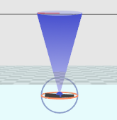
A transducer point pointing straight upwards from a fixed platform on the sea/lake/river bottom; the transducer is sitting on the platform 0.74m from the bottom of the platform which is on the sea floor. The water level is 32m from the transducer face.
- Specify the Z coordinate of the water level relative to the platform. This is given by the range of the water surface on the echogram and the Z vertical offset of the transducer. Z coordinate of the water level is -32 + -0.74 = -32.74 m.
- The Z vertical offset of the transducer on the platform is -0.74m. The bottom of the platform is on the sea floor and is deemed to be Z = 0 for the platform reference.
- Transducer Elevation is 180°. Note: The Transducer Beam rotation can be useful in the calculation of traveling direction of acoustic targets.
- Use Flip echogram vertically under Other on the Echogram Display page of the Variable Properties dialog box to orient the echogram data.
The illustration (above) is configured with Platform Properties dialog box Position page settings and Transducer Properties dialog box Geometry page settings.
Notes:
- You may define the pointing direction of the transducer with whichever pair of angles is most convenient for your application but the rotation angle will be the same, whichever pair of angles you choose to define the pointing direction.
- For a transducer with an elevation of 0° (that is, vertically downward pointing), the azimuth angle is logically equivalent to the transducer rotation. Echoview does not adjust the rotation angle on the dialog if you specify an azimuth without any elevation. We recommend, for clarity, that you do not use a non-zero azimuth with a zero elevation.
- See also: The Upward facing transducer echogram example, Working with a submerged platform and the Geometry page of the Transducer Properties dialog box.
See also
About platforms
About echograms
EV File Properties, Echogram page
Transducer Properties dialog box
About draft
Logged draft warning
Depth, Range and Altitude
About beam geometry
What is affected by transducer geometry?
About heave compensation
Transducer geometry illustrated - fixed platform