Transducer geometry illustrated
The settings from the Platform Properties dialog box and the Transducer Properties dialog box provide the reference points and planes for fish track geometry.
The Platform: Specifying position and attitude on the earth
Moving platform
- Specify a GPS data source for latitude and longitude.
- Can specify X, Y location of the GPS antenna on the platform.
- Can specify an associated Distance data source.
- Can specify a Heading data source.
- Specify Altitude of platform system reference point.
Fixed platform
- Specify Latitude and longitude.
- Can specify the Fixed heading (North) or a Heading data source.
- Specify Altitude of platform system reference point.
Z coordinate of the water level
- Specify Z coordinate of the water level in relation to the Altitude of the platform system reference point. The value of the Z coordinate of the water level represents the water level at the start time of the echogram data.
Heave source
- Specify heave data source for the platform.
Note: Roll and Pitch data are not applied to the platform but may be applied to raw variables.
The Transducer: Specifying location and orientation on the platform
Transducer location
X and Y values specify the location of the transducer with respect to the X, Y plane of the platform.
The Z value is the transducer vertical offset with respect to the Altitude of the platform system reference point.
Transducer orientation
Values for Elevation, Azimuth and Beam rotation describe the orientation of the transducer on the platform.
Example: One horizontal transducer on a fixed platform
|
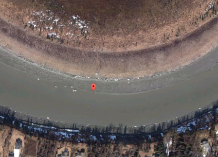
Figure 1: Google Map display for the location of a transducer on a fixed platform. Up is North. |
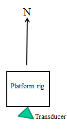
Figure 2: Schematic (map view) for a fixed platform with a transducer at an Azimuth of 190 degrees. |
Platform Position and Transducer Location
Platform Position settings
- Fixed platform
- Latitude = 60.518541. Longitude = -151.163664
- Altitude of platform = 0 m.
- Z coordinate of the water level = 0 m.
- Heading source = Heading Fixed North
Transducer Location settings
- Current transducer locations X = 0 m, Y = 0 m. These are set under the Location, Transducer section in Figure 3.
- Current transducer location Z = 0.5 m. This is set under the Location, Transducer section in Figure 3.
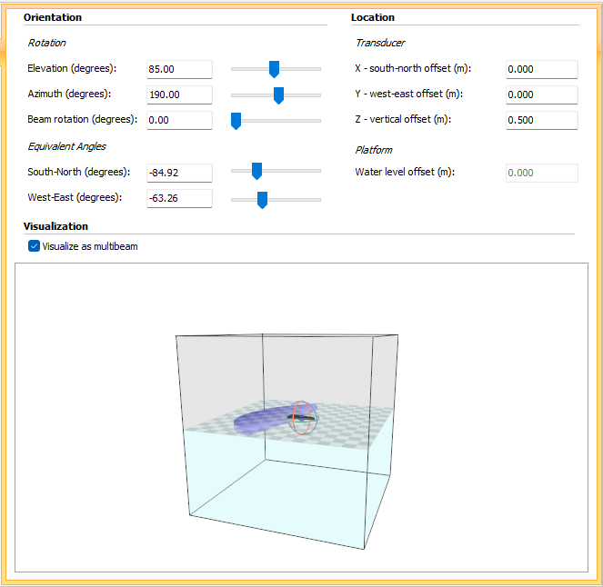
Figure 3: One transducer on a fixed platform, visualized as multibeam. Transducer Properties dialog box: Geometry page, containing Orientation and Location settings.
Transducer Orientation
Transducer Orientation settings
- Elevation = 85 degrees is displayed as the vertical angle of the pink-colored circle around the dark grey transducer in Figure 3.
- Azimuth = 190 degrees is displayed as the horizontal angle of the teal-colored circle around the dark grey transducer in Figure 3.
- Beam rotation = 0 degrees is displayed as zero degrees rotation of the wide, purple fan from the dark grey transducer in Figure 3.
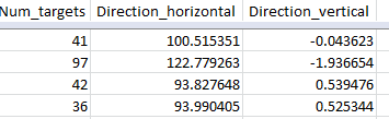
Scene, Fish track: Direction_horizontal, Direction_vertical
|
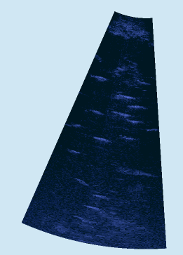
Figure 4: Map view (up is North) of an imaging sonar ping curtain in a Scene. The beam fan is oriented correctly and located under the water. |
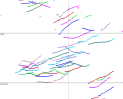
Figure 5: (Top) Fish tracks in single target echogram derived from multibeam target detection on imaging sonar data. |
Planes and reference directions for Direction_horizontal and Direction_vertical
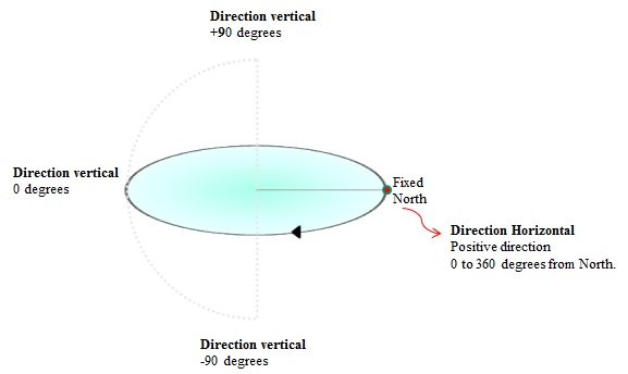
Figure 6: Fixed platform Direction_horizontal and Direction_vertical reference planes and directions.
See also
About transducer geometry
About platforms
Sound Metrics notes