Standard sphere calibration
Refer to the Calibrating an echosounder and Calibration Assistant pages.
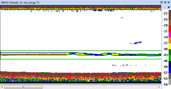
Sv variable
Figure 1: Simrad Ek60 Sv data with a -35 dB calibration sphere. Green lines mark the 18 m and the 21 m ranges. The calibration sphere is located between these two ranges. The Simrad TransducerGain for the Sv variable is adjusted so that the measured Sv of the calibration sphere matches the theoretical Sv of the calibration sphere.
|
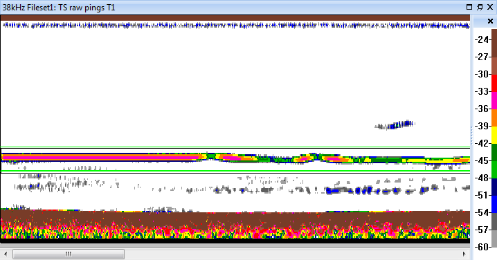
TS variable
Figure 2: Simrad Ek60 TS data with a -35 dB calibration sphere. The calibration setting TransducerGain for the TS variable is adjusted so that the measured TS of the calibration sphere (represented by detected single targets) is -35 dB.
|
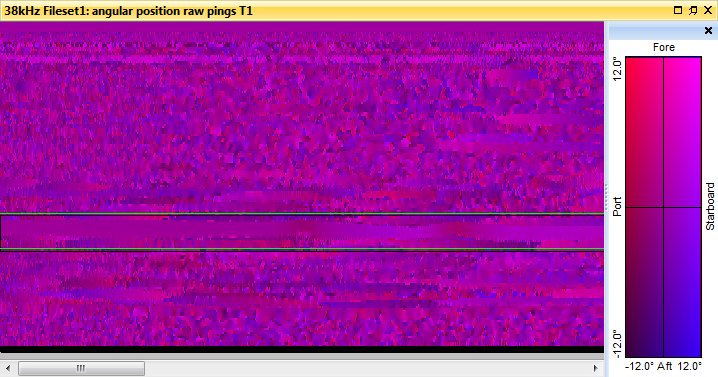
Angular position variable
Figure 3: Simrad Ek60 angular position data with a -35 dB calibration sphere. The Angular position variable and the TS variable are used by a single target detection algorithm to find single targets associated with the calibration sphere.
|
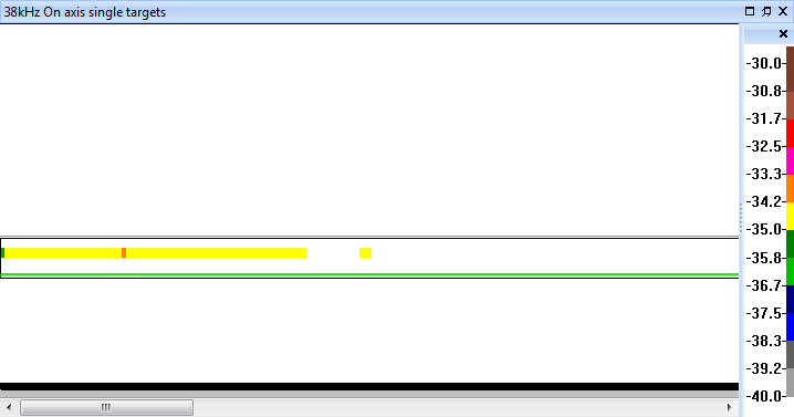
Detected single targets
Figure 4: Single target data derived from Simrad Ek60 TS and angular position data (with a -35 dB calibration sphere). Single target detection (via an Echoview virtual variable) is used to detect echoes from the calibration sphere. Note the limited variation of TS for the detected single targets.
|
See also
Examples of echogram interpretation
Calibrating an echosounder
Calibration sphere modeling and references