About heave compensation
Platforms, whether moving or fixed, may be subject to vertical motion. Commonly, this is called heave but it may also result from the vertical motion of an AUV for example. Echoview reads data recorded by heave sensors or altitude sensors as line data and you can use the line as a Heave source to apply heave to echogram data. Heave changes the vertical position of samples; it affects their depth, but not their range. The Heave source is used to adjust the depth of each ping so that its samples lie close to their true depths. Range, which is a measure of the linear distance from the transducer face, is unaffected by heave.
The Heave source is a property of the platform. The Platform Properties dialog box allows the selection of a single Heave source line, but operators may be used to combine multiple lines to create it. For information about deriving a heave line from heave data refer to About heave data.
When heave is applied, each ping will no longer start at the same depth. This has implications for Echoview's ping geometry requirements and may therefore impact certain subsequent data-processing operations, e.g., use of virtual variables that are reliant on a fixed relationship between range and depth over time.
Single, split and dual beam data
The heave for a single beam ping is the depth of the Heave source line at the ping time, rounded to the nearest sample height. In some cases the heave may be visibly non-zero yet the samples do not move because it is rounded to zero. The heave applied to detected single targets is based on the rounded heave of the operand variable. However, heave is not rounded for raw single target variables and sounder-detected bottom lines.
Single beam echograms only display heave corrected data in Depth mode.
Operators with single beam operands that assess an interval of heave corrected pings or ping-to-ping calculations use the sample index.
Multibeam data
Heave for multibeam data is applied as a numerical offset to the whole ping. Refer to Figure 4 Multibeam data and heave.
Multibeam echograms can display heave corrected data in Depth or Range mode.
Single beam virtual variables derived from multibeam data apply heave as for single beam data. The applied heave offset is rounded to the nearest sample thickness. As a result, a sample in single beam virtual variable and the matching sample in the original multibeam data may differ by a value between zero and half of one sample thickness.
3D school detection and multibeam operators that assess an interval of heave corrected pings or ping to ping calculations use the sample index.
- Only raw and editable lines can be used directly as the Heave source. To use a virtual line or a sounder-detected bottom line, create an editable line from it and use that.
- The heave of the ping under the mouse is displayed in the Navigation section of the Details dialog box.
- Heave_source, Heave_min, Heave_max and Heave_mean export variables may be selected under Analysis domain on the Export page of the EV File Properties dialog box.
- Heave compensation may change the number of pings within an analysis domain by shifting a ping partly or completely out of the analysis domain (as shown by the state of the analysis hatching). As a result values like the Thickness_mean and Thichness_mean-dependent quantities may change.
- Heave compensation affects the export of range based analysis variables - they are set to a special export value of -9999.0.
- Operator interval examples include a window of pings, pings in a convolution matrix or pings in a cell or layer.
- Prior to Echoview 6, the Towed body operator offered a limited method to account for vertical moment and its use was for visualization only.
How is echogram data affected?
The following topics model the effects of heave.
- A platform on the water
- A submerged platform
- Heave and actual echogram data
- Multibeam data
A platform on the water
Figure 1 illustrates how heave affects echogram data collected from a platform on the water. "Data collection" shows a platform P (with a downward facing echosounder) affected by swell where (+1, -1) show the extent of the changes in depth. Such changes can be recorded by a heave sensor. The blue line represents a reference depth of zero. There are fish in the water column and the bottom is flat.
"Echogram" shows a traditional echogram of the resulting data. There is no heave compensation and the transducer is at zero range and zero depth. The physical bottom is actually flat but the bottom samples appear wavy. This is because a transducer at the top of the swell records an echo at an increased range. Similarly, a transducer in the trough of a swell records an echo at a decreased range.
"Echogram with heave compensation" shows the Heave source line and the effect of heave compensation. The platform moves up and down with the Heave source line. The range reference zero follows the heave line. The ranges for the samples are unaffected, however their depths and their locations on the echogram are offset by the Heave source line.
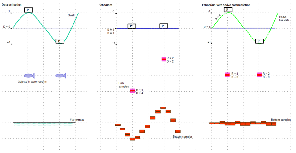
Figure 1: A floating platform and heave compensation.
A submerged platform
Figure 2 illustrates how heave affects echogram data collected from a submerged platform. Platforms like a towed body, AUV or ROV can travel vertically in the water column. "Data collection" shows a platform with a downward facing transducer. The vertical path of the platform can be recorded by a heave or altitude sensor. The blue line represents a reference depth of zero. There are fish in the water column and the bottom is flat.
"Echogram" shows a traditional echogram of the resulting data. There is no heave compensation and the transducer is at zero range and zero depth. The physical bottom is actually flat but the bottom samples are not flat. This is because as the platform descends the range decreases, bringing the bottom closer.
"Echogram with heave compensation" shows the Heave source line and the effect of heave compensation. The platform moves up and down with the Heave source line. The range reference zero follows the heave line. The ranges for the samples are unaffected, however their depths and their locations on the echogram are offset by the Heave source line.
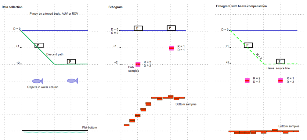
Figure 2: A submerged platform and heave compensation.
A heave example
Figure 3 shows heave in actual echogram data. The left echogram displays single beam data with no heave compensation applied. The right echogram is the same data with heave compensation applied. The yellow line is recorded heave data. The purple dashed line is the sounder-detected bottom line.
|
|
|
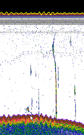
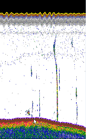
Figure 3: Compensating actual data.
Multibeam data
Heave compensation is not rounded before being applied to a multibeam ping. Figure 4 shows a simplified time series of multibeam pings. The blue line represents a reference depth of zero. The pink oblong represents a large feature (like a school). The dashed green line represents heave. Heave compensation offsets all the data of the middle ping downwards by the same amount, realigning the feature with its counterparts in pings 1 and n.
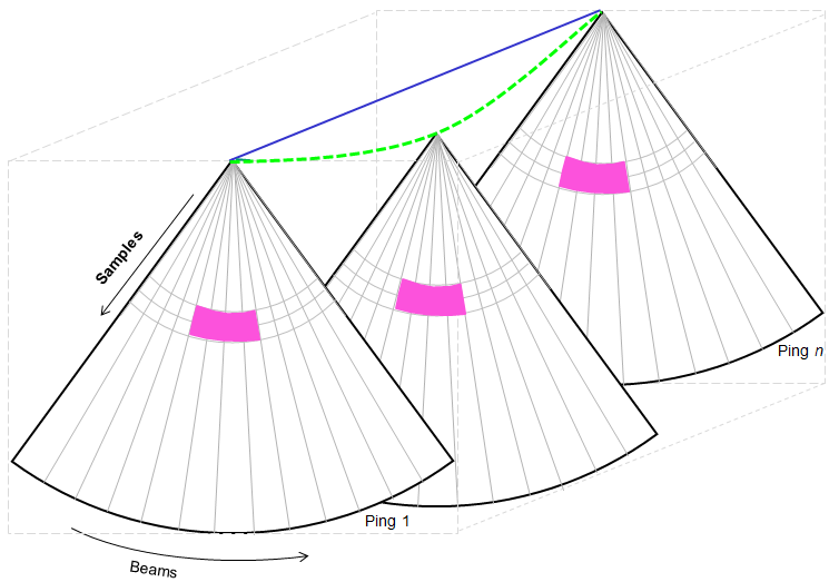
Figure 4: Compensating multibeam data.
See also
About depth, range and altitude
About pitch data
About roll data
About heave data
About platforms
Platform Properties dialog box
Transducer geometry