HTI sample data to Sv, TS and angular position
Values in sample files
HTI Sample (.smp) files that contain all calibration and settings information have the following values for each sample.
HTI Sample (.smp) files which require .cfg and .cal files to be added to a fileset, will also have the following values for each sample. Refer to HTI data files for more information.
|
Value |
Description |
|
ang_UD |
The electrical angle (phase difference) between the up and down halves of the split-beam transducer (see About beam geometry) |
|
ang_LR |
The electrical angle (phase difference) between the left and right halves of the split-beam transducer (see About beam geometry) |
|
det20 |
The received voltage signal with 20Log(R) TVG applied and absorption (alpha) losses removed |
|
det40_i |
The in phase component of det40 |
|
det40_q |
The quadrature component of det40 |
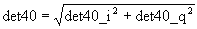
det40
det40 is the received voltage signal with 40Log(R) TVG applied and absorption (alpha) losses removed. Sample files created before April 2003 contain a single det40 value for each sample. Sample files created after April 2003 contain a det40_i and det40_q value for each sample. When Echoview reads a sample file containing det40_i and det40_q it combines them to calculate det40 as follows:
Calculating Sv, TS and angular position
For each sample Echoview displays in an echogram it will calculate as required:
-
the ping time
-
the sample range, and
-
the sample value(s) (Sv, TS or minor and major axis angles).
Note: The conversions on this page are derived from the HTI Operator's Manual for the Model 241/243/244 Split Beam Digital Echosounder System (Version 1.7 1998) and through correspondence with HTI directly.
Calculation of ping time
The ping time is stored in the .smp file in the ping header. Where the a ping has the same time as the previous ping, Echoview will ignore the recorded ping time and recalculate the ping time by adding the relevant period interval (stored in the .cfg file or .smp file) to the time of previous ping (in the file).
Calculation of sample range
The range of the sample is calculated as follows:
fs = 12 kHz - the known sampling frequency
Ts = c / fs - the sample thickness in meters (where c is sound speed and is read from the .cfg file or the .smp file)
Range = Ts × ( i - 0.5 ) where i is the number of the sample within the ping starting from 1
Calculation of Sv, TS and angular position
Sv, TS and angular position are calculated according to:
Sv = 20log(det20) - SL - RG - G20 - TVG - Xcorrection - 10log(πcBτe) + Cal
TS = 20log(det40) - SL - RG - G40 - TVG + Cal
minor axis angle = ang_UD / αV
major axis angle = ang_LR / αH
| Cal | = | The CalibrationOffset displayed on the Calibration page of the Variable Properties dialog box in Echoview (default = 0) |
| SL | = | Source_Level_n where Transmit_Power = Transmit_Power_n |
| Xcorrection | = | 20log(Xcollection/Xcalibration) |
| τe | = | τ if Chirp_bandwidth = 0 |
| = | 0.72 ms if Chirp_bandwidth = 2.5 kHz | |
| = | 0.36 ms if Chirp_bandwidth = 5.0 kHz | |
| = | 0.18 ms if Chirp_bandwidth = 10.0 kHz |
and whenever required, Echoview reads from the relevant .cfg and .cal files or directly from .smp files containing calibration and settings data:
|
Symbol |
Name |
Units |
File |
Section |
|
Chirp_BandWidth |
kHz |
.cfg |
[Sequence_s SamplePeriod_p Settings] |
|
|
Period_Interval |
s |
.cfg |
[Sequence_s SamplePeriod_p Settings] |
|
|
τ |
Pulse_Width |
s |
.cfg |
[Sequence_s SamplePeriod_p Settings] |
|
RG |
Receiver_Gain |
dB |
.cfg |
[Sequence_s SamplePeriod_p Settings] |
|
c |
Speed_sound |
m/s |
.cfg |
[Sequence_s SamplePeriod_p Settings] |
|
Transmit_Power |
dB re 1W |
.cfg |
[Sequence_s SamplePeriod_p Settings] |
|
|
Xcollection |
Tvg_Crossover |
m |
.cfg |
[Sequence_s SamplePeriod_p Settings] |
|
TVG |
Tvg_Gain |
- |
.cfg |
[Sequence_s SamplePeriod_p Settings] |
|
B |
Beam_Pattern_Factor |
- |
.cal |
[Beam Dimension Values] |
|
αH |
Horizontal |
- |
.cal |
[Ratio Values] |
|
αV |
Vertical |
- |
.cal |
[Ratio Values] |
|
SL |
Source_Level_n |
dB |
.cal |
[Source Level Values] |
|
G20 |
Log_20 |
dB |
.cal |
[Through System Gain] |
|
G40 |
Log_40 |
dB |
.cal |
[Through System Gain] |
|
Xcalibration |
Tvg_Crossover |
m |
.cal |
[Through System Gain] |
|
Transmit_Power_n |
dB re 1W |
.cal |
[Transmit Power Settings] |
Notes:
- G20 and G40 are referred to as 'transducer sensitivity' on the Details dialog box (F9). This follows the convention on page 7-4 of the HTI Operator's Manual for the Model 241/243/244 Split Beam Digital Echosounder System (Version 1.7 1998) and discussions with HTI.
- The .cal file that is associated with a variable is determined by the mux port that was used. The mux port that was used can be identified:
- in the variable name, see Raw Variables derived from HTI data files
- on the Data File Information dialog box for the .cal file
- HTI 48 kHz interpolated data is a result of the application of an HTI 48 kHz interpolation algorithm applied to the sample data in the *.smp file followed by the application of the algorithms above.
- TVG is applied to samples with ranges greater than 1 meter.