Single target detection - wideband algorithm
This operator applies a modified split beam method 2 algorithm that considers pulse compressed power data, a peak's maximum TS value and applies beam compensation and angle constraints to the peak selection criteria. Single Target detection settings are used in the algorithm (which is a superset of the single beam (method 2) algorithm, additions to the basic algorithm are displayed in orange.
Echoes in the water column on a TS pulse compressed wideband echogram appear narrower than matching echoes on related TS wideband echograms. Pulse compression introduces a range offset that is based on the size of the matched filter and the start range for the physical target. The Single target detection - wideband echogram derives its targets from pulse compressed data and consequently the start of a detected target occurs (and is displayed) at the range of the peak sample of the echo. For more information refer to Target strength and range in the echo envelope.
The single target detection - wideband operator and the algorithm are under active development.
Notes:
- Some file formats calculate the absorption coefficient rather than reading the value from the file.
- See Single target pulse properties for illustrations on how target TS and normalized pulse lengths are determined. The page also offers an illustration of a single target pulse with respect to single beam detection settings.
- In Method 2 operators, the TS threshold is applied to TS data after the targets are detected. So with the split-beam (method 2) operator the threshold applies to the compensated TS.
- See also Using a SoundSpeedProfile: Notes
Variable properties
The first operand must be a TS pulse compressed wideband variable. The second operand can be an angular position pulse compressed wideband variable; it is left to you to select the angular position data that corresponds to the selected TS data.
When Operand 2 is None, the operator uses the Operand 1 data and does not use Beam compensation or Exclusion angles. In this case, it is assumed that detected single targets are all on the beam axis.
The single target detection parameters are set on the Single Target Detection page of the Variable Properties dialog box. Lines can also be selected for excluding targets above or below a line. Apart from limiting the target detection range, exclusions will also speed up processing, since less data will then be screened for single targets.
|
Parameter |
Units |
Allowed range |
Default value |
|
TS threshold (see note) |
dB re 1m2 |
-120 to 20 |
-50 |
|
Pulse length determination level (PLDL) |
dB re 1W |
0.01 to 30 |
6 |
|
Minimum normalized pulse length |
- |
0.01 to 10 |
0.5 |
Maximum normalized pulse length |
- |
0.01 to 10 |
1.5 |
|
Minimum target separation |
m |
0 to 1 |
0 |
|
Beam compensation model |
Simrad LOBE |
Simrad LOBE |
|
|
Maximum beam compensation |
dB re 1m2 |
0 to 35 |
4.0 |
|
Maximum standard deviation of minor-axis angles |
degrees |
0 to 45 |
0.6 |
|
Maximum standard deviation of major-axis angles |
degrees |
0 to 45 |
0.6 |
Notes:
- You should also check the effects of Calibration settings.
- TVG (and any TVG range correction) are applied after targets are detected. The TVG range correction algorithm applied is specified on the Calibration page of the operator. It is initially inherited from the Calibration page of the first operand.
- The default value for PLDL is correct by convention and theory. It is not independent of other settings, and it is not normally changed.
- See Beam compensation for details on the Beam compensation models.
- The maximum standard deviation settings for minor-axis and major-axis angles are expressed in mechanical degrees.
Algorithm
'Pulse compressed wideband' input operands allow access to underlying pulse compressed wideband power data before TVG is applied.
The single target detection - wideband algorithm determines all power peaks that may indicate single targets and then rejects pulses that are separated by less than Minimum target separation value. The values for the single target detection settings are used as selection criteria against which samples are judged. The criteria are applied in order, and only samples that pass one criterion are considered in the next. Once single target samples are identified TVG is applied. The TS threshold criteria is then applied. Finally, uncompensated Complex TS and compensated Complex TS are calculated.
High resolution of pulse compressed data requires the use of the PulseCompressedEffectivePulseDuration (rather than the TransmittedPulseDuration) with normalized calculations.
- Minimum normalized pulse length
- Maximum normalized pulse length
- Pulse length at PLDL (normalized)
- Pulse length at 6 dB (normalized)
- Pulse length at 12 dB (normalized)
- Pulse length at 18 db (normalized)
The Minimum target separation setting prevents the detection of targets that are close together. This can be useful when analyzing calibration sphere data and configuring a detection of a single line of targets to represent the calibration sphere signal. The algorithm considers pulse compressed Power and then pulse compressed TS data on a ping by ping basis.
Definitions for single target detection - wideband settings and algorithms:
n = the samples for the candidate peak, it is defined by the samples above the value for (peak sample value - PLDL).
m = the first sample in the candidate peak pulse envelope.
p = the peak sample in the candidate peak pulse envelope.
ri = uncorrected range (m) of sample i.
Pi = Power (dB) value for sample i.
Pp = Power (dB) value for the peak sample in the candidate peak pulse envelope.
c = SoundSpeed (ms-1) on the Calibration page of the operator Properties dialog box.
τeff = PulseCompressedEffectivePulseDuration (s) on the Calibration page of the operator Properties dialog box.
AbsorptionCoefficient = AbsorptionCoefficient (dB/m) on the Calibration page of the operator Properties dialog box.
TS_uncomp = the uncompensated TS (dB) of the target.
TS_comp = the compensated TS (dB) of the target.
Corr = Correction (dB) estimated by a selected Beam compensation model, and applied to TS_uncomp.
Simrad split beam compensation model: TS_comp = TS_uncomp + CorrSimradSplitBeam
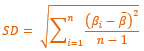
βi = Represents the i-th minor-axis or major-axis angle in the candidate peak pulse envelope that contains n samples.
The algorithm begins by removing data for which no targets need to be determined (i.e. data above and below the exclusions lines) and then processes the data in two main phases:
Phase I: Determine all power peaks that may indicate single targets
In this phase, Echoview detects all peak values that could indicate the presence of a single target. For a power value to be retained as a peak value it must satisfy following peak selection criteria.
Peak selection criteria
The criteria are applied in this order, and only samples that pass the preceding criterion progress to be checked against the next.
- The pulse compressed power value must be a local maximum. If the local maximum consists of more than one sample with the same pulse compressed power value, then the first sample in this sequence is used.
- The beam compensation value must not exceed the Maximum beam compensation (see Simrad split beam compensation).
- The candidate-peak normalized pulse length (made up of n sample points) must be within the limits set by Minimum normalized pulse length and Maximum normalized pulse length. See Pulse envelope determination (below).
- The standard deviation of the angles (minor and major axis) of all samples within the pulse envelope must not exceed the Maximum standard deviation of angles allowed. See Pulse envelope determination (below).
Notes:
- A peak sample value preceded or followed by a no data sample is not detected as a target.
- TS values that change from negative to positive or vice versa are considered invalid for peak selection.
Pulse envelope determination
The pulse envelope consists of all samples surrounding the peak sample (p) which are above the Peak power - Pulse length determination level. The pulse length (for the peak selection criteria) is determined as the distance between the first sample (m) and last sample within the pulse envelope.
The (sample) standard deviation of the angles within the envelope is calculated for the minor-axis and major-axis angles independently as follows:
Where:
Phase II: reject pulses based on Minimum target separation
Based on the set of candidate pulse-peaks obtained in Phase I, single targets are determined as follows:
- Pulses are screened in order, from low to high depth values.
- The target range is the range of the peak TS pulse compressed wideband sample.
- The target TS value is calculated using:
TS_uncomp = Pp + 40log(r) + 2×AbsorptionCoefficient×r
- If the target TS value is less than the TS threshold, the target is rejected.
- If two pulses are separated by less than the Minimum target separation, the pulse with the lower TS value is rejected.
- The uncompensated target TS value is corrected for the selected Beam compensation model.
TS_comp = TS_uncomp + Corr
Single target properties
The table below describes how algorithm specific single target properties are calculated. See About analysis variables for a complete list of single target properties
|
Analysis variable |
Unit |
Description |
|
Complex TS_uncomp |
dB re 1m2 |
Uncompensated Complex TS of a single target. |
| Complex TS_comp | dB re 1m2 |
Compensated Complex TS of a single target. Compensation is calculated using the selected Beam Compensation Model. |
|
Target-range |
m |
Range of a single target. |
|
Angle-minor axis |
degrees |
Minor-axis angle of the peak sample |
|
Angle-major axis |
degrees |
Major-axis angle of the peak sample |
See also
About Single target detection
Single target detection algorithms
Echoview and Simrad algorithms
References
Single target pulse properties