About calibration settings
Calibration settings are values that are used to achieve calibrated data within an acoustic variable.
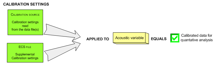
Echoview's calibration model takes calibration settings from data, uses default settings where none are available and modifies calibration values using an ECS file. To achieve calibrated data for quantitative analysis, you must verify and correct calibration settings especially when the Message box flags the use of default values or when you know there are incorrect settings recorded with your data. Default values enable Echoview to display echogram data, however the values may be unsuitable for your data. Refer to calibration workflow for more information.
- Echoview calibration setting values
- Additional uses of calibration settings
- Deprecated calibration names
Note: An ECS file may affect multiple EV files or multiple variables. For more information refer to Echoview Calibration Supplement files.
Echoview calibration setting values
Echoview calibration setting names and values are displayed on the Calibration page of the Variable Properties dialog box. Data file values that have been used since the data was loaded or the ECS file was added, saved or removed are displayed in black text. Default values that have been used are displayed in orange text. Data file or ECS values that have been read but not used are displayed in gray text.
Calibration setting values can be changed by using an ECS file, that is added to a fileset through the Calibration section of the Filesets window. Refer to Echoview calibration supplement files for information about the grammar and syntax of ECS files. Echoview can auto-generate an ECS file based on the calculations performed with your data. You can then Copy-Paste calibration setting information to it from the:
- Settings section of the Calibration page of the Variable Properties dialog box
- Settings section of the Calibration Information dialog box
Most settings on the calibration pages are used for calculating data point values and data point ranges and must therefore be correctly set for each variable to achieve meaningful displays and analyses. For information on recording calibration settings with exports see Exporting Data.
Settings on the Calibration page of the Variable Properties dialog box are directly associated with the data within the variable. The selection of a transducer and the properties of the transducer used to collect your data should be defined prior to entering calibration settings. See About transducer geometry.
Notes:
- Echoview initially calculates and displays data using default calibration settings that are not useful for quantitative analyses. Until you change these values, the data values that are displayed in your echograms and used for analyses will be incorrect. Newly modified calibration settings are applied when you recalculate or step through the pings of the echogram.
- Calibration settings on the Variable Properties dialog box use colored-text cues to indicate the processing that has been done since the data and ECS files were loaded. For more information refer to Calibration page: Settings and Notes.
- Changes in calibration settings used for range calculations may shift ping data in the depth dimension but will not automatically adjust the position of regions and lines. You should review any existing regions and lines to ensure they are still valid. For more information refer to Range calculation effects on regions and lines.
- Calibration settings for analysis exports are specific to each variable, and are not included in export data.
- Data management tips:
- To ensure that you have a permanent record of the calibration settings for your export, create a read-only folder to store your export data.
- For each export, save a copy of the EV file to the folder path of the export. If you used an ECS file, save a copy of the ECS file as well.
A summary of how the calibration settings are used for the variables in each data set is available on the following pages:
- Calibration settings for text data
- Calibration settings for ARIS data
- Calibration settings for ASL Environmental Sciences data
- Calibration settings for BioSonics data
- Calibration settings for Blueprint Subsea Oculus data
- Calibration settings for BlueView data
- Calibration settings for DIDSON data
- Calibration settings for EchoListener data
- Calibration settings for Echoview Data File Format data
- Calibration settings for Furuno ETR-30N data
- Calibration settings for Furuno FQ80 data
- Calibration settings for Furuno FCV30 data
- Calibration settings for Furuno FCV38 data
- Calibration settings for Furuno FSV-25 (netCDF4) data
- Calibration settings for Furuno FSV-30 (Research version) data
- Calibration settings for HAC data
- Calibration settings for HTI data
- Calibration settings for Kongsberg EM 3002, EM 3002D and EM 710 data (*.all)
- Calibration settings for Kongsberg EM systems (*.KMall)
- Calibration settings for Kongsberg M3 and Flexview data
- Calibration settings for Navico Group Lowrance data
- Calibration settings for Norbit data
- Calibration settings for Nortek data
- Calibration settings for PAS data
- Calibration settings for R2Sonic data
- Calibration settings for RD Instruments workhorse data
- Calibration settings for RESON data
- Calibration settings for Teledyne Odom data
- Calibration settings for Simrad Omnisonar netCDF4 data
- Calibration settings for EK500 telegrams logged with Ex500
- Calibration settings for EK500 telegrams logged with Ex60
- Calibration settings for Simrad EK15 raw data
- Calibration settings for Simrad EK80 raw data
- Calibration settings for Simrad Ex60 raw data
- Calibration settings for Simrad Ex70 raw data
- Calibration settings for Simrad SM2000 data
- Calibration settings for Simrad SM20 data
- Calibration settings for Simrad ME70 raw data
- Calibration settings for Simrad MS70 raw data
- Calibration settings for Simrad SH80 data
- Calibration settings for Simrad SH90 data
- Calibration settings for Simrad SC90 data
- Calibration settings for Simrad SP70 data
- Calibration settings for Simrad omnisonar netCDF data
- Calibration settings for Simrad SX90 data
- Calibration settings for Sonic data
- Calibration settings for virtual variables
- Calibration settings for WASSP data
Additional uses of calibration settings
Some calibration settings are used for purposes other than calculating the data point values or ranges.
Calculations affected by specific calibration settings are:
- Time-varied thresholds
- Background noise analysis variables
- Corrected schools analysis variables
- Beam volume sum
- Single target and target length displays
- Frequency Response graph
- Virtual variables created by single target detection operators
- Multibeam bottom detections export files
- Wedge volume sampled
- Sounder-detected lines, range to depth calculations
- Calibration Assistant
The tables below describe which calibration settings affect these calculations. If you intend using TVG, background noise analysis variables, corrected schools analysis variables, beam volume sum or single targets the calibration settings listed must be entered correctly for the specified variables.
Note: The tables apply to both raw and virtual variables from data logged with any echosounder.
Sv variables
|
Setting |
Affects |
|
Calibration page of Variable Properties dialog box |
|
|
Background noise analysis variables. |
|
|
Corrected schools analysis variables. Sample thickness. |
|
|
Sample thickness. |
|
|
SimradDraftLogging (where available) |
Corrected schools analysis variables. |
|
Frequency Response graph. |
|
|
Multibeam bottom detections export (Athwartship). |
|
|
Corrected schools analysis variables. |
|
TS variables
|
Setting |
Affects |
|
Calibration page of Variable Properties dialog box |
|
|
Time-varied thresholds |
|
|
Sample thickness. |
|
|
Virtual variables created by single target detection operators using the PLDL and normalized pulse length. |
|
Single target and target length variables
|
Setting |
Affects |
| Calibration page of Variable Properties dialog box | |
Calibration Assistant, Output Generic, Narrowband. See also the Calibration Assistant note below. |
|
|
MajorAxisAngleOffsetTableWideband MajorAxisBeamWidthTableWideband MinorAxisAngleOffsetTableWideband |
Calibration Assistant, Output Generic, Wideband |
FrequencyTableWideband MajorAxisAngleOffsetTableWideband MajorAxisBeamWidthTableWideband MinorAxisAngleOffsetTableWideband MinorAxisBeamWidthTableWideband |
Calibration Assistant, Output Simrad Specific, Wideband |
|
Single target display thickness1 Virtual variables created by single target detection operators using the PLDL and normalized pulse length. Sample thickness. |
|
|
Single target display thickness1 Sample thickness. Calibration Assistant, Output Simrad Specific, Narrowband/Wideband Calibration Assistant, Output Generic, Narrowband/Wideband |
|
|
Sample thickness. |
|
Beam compensation of single targets detected in Echoview. Beam volume sum algorithm: may be used in the default single target beam volume angle calculation. Wedge volume sampled algorithm: may be used in the default calculation of across-track single target beam angle. Calibration Assistant, Output Simrad Specific, Narrowband Calibration Assistant, Output Generic, Narrowband |
|
|
|
Calibration Assistant, Output Simrad Specific, Narrowband Calibration Assistant, Output Generic, Narrowband |
| Calibration Assistant, Output Simrad Specific, Narrowband | |
|
|
Wedge volume sampled algorithm(when you want to override the default Major-axis 3 dB beam angle being used as the inital acrosstrack beam angle or when the transducer is elliptical or is not pointing vertically down). |
Notes:
- 'Single target' refers to single target data from single target detection variables. The calibration settings for raw single target variables can be different to single target detection variables.
- 1 Except for virtual variables in the Single target manipulation operators group. The Single target display thickness for these virtual variables is inherited from the first operand.
- 2 Except for Target length variables, where the calculation of Beam volume sum is not supported.
- The Calibration Assistant is launched from a selection or region on a single target detection variable and considers the calibration values of the contributing operands when calculating calibrated settings.
Deprecated calibration names
Echoview supports multiple names for a calibration setting name. Deprecated names used in existing EV files and scripts and current calibration names for the same setting are handled seamlessly.
Affected names include:
- TransducerGain: previous alias is Ek60TransducerGain
- PulseDuration: previous alias is TransmittedPulseLength
- SaCorrectionFactor: previous alias is Ek60SaCorrection
- PulseDurationLogging: previous alias is TransmittedPulseLengthLogging
- EffectivePulseDuration: previous alias is EffectivePulseLength
- PulseCompressedEffectivePulseDuration: previous alias is PulseCompressedEffectivePulseLength
Note: The single target data export outputs Pulse_duration in place of Transmitted_pulse_length.
See also
About calibrated data
Calibrating an echosounder
Calibration settings for virtual variables
About time varied gain